Large Scale Central

Servo controlled turnouts/points

My 4 Channel relay module arrived today. For $7 it didn’t make sense to solder up a bunch of relays. This board has 4 SPDT 12V relays that can be triggered via optocoupler with either a high or low logic signal.

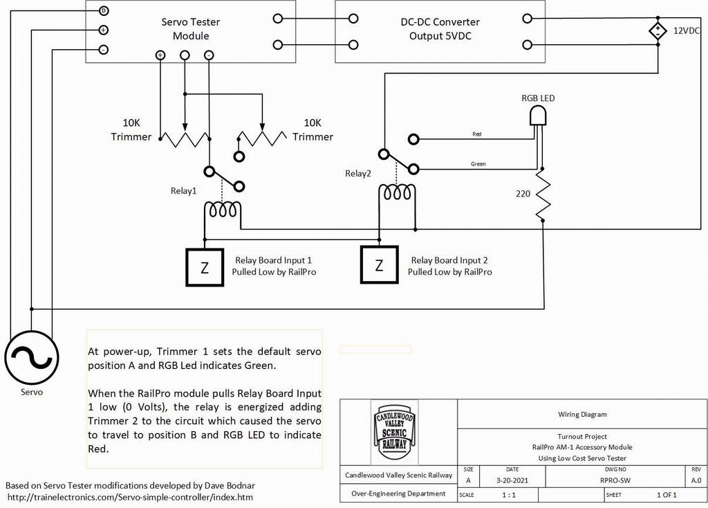
RailPro lamp outputs are a switched ground, therefore function as a logic low signal. I daisy chain the input of two channels for one turnout. One channel triggers the servo movement, replacing the SPST switch in the Bodnar circuit. The other channel will be for position feedback to RailPro [If I am successful at using their turnout program] and also supplies power to the position indicator LED. For simplicity, and since I have them in-stock, I am using common Anode RGB LEDs for the position indication.

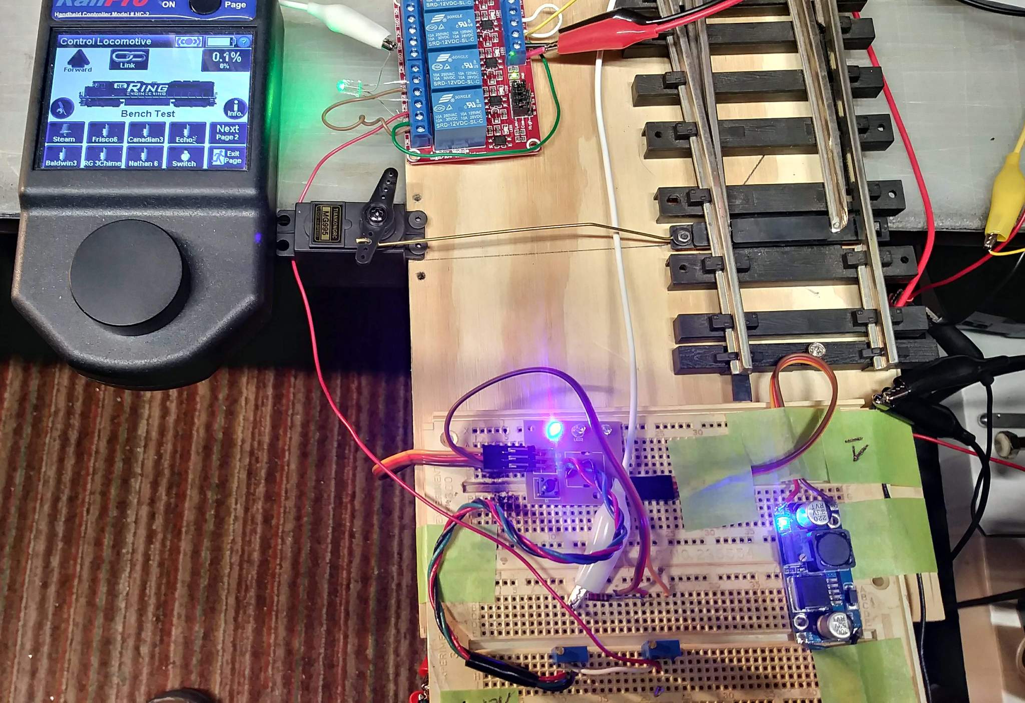
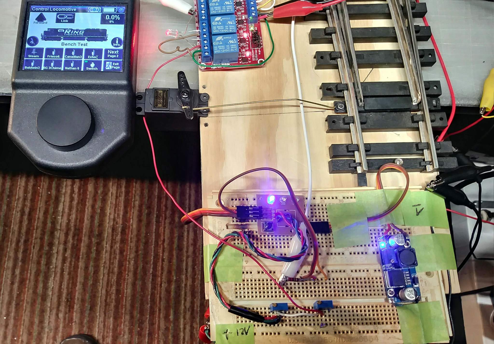
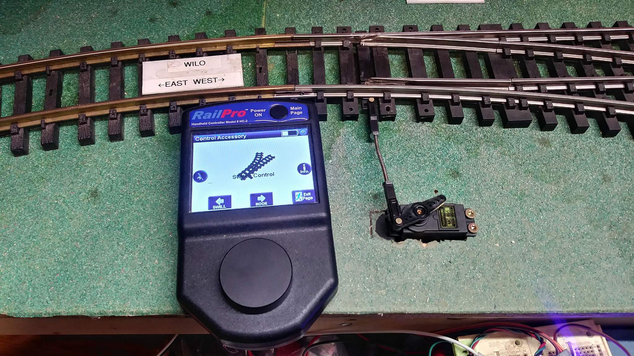
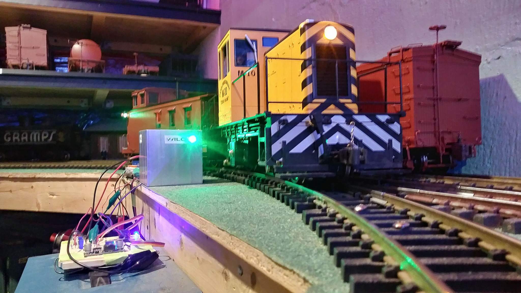
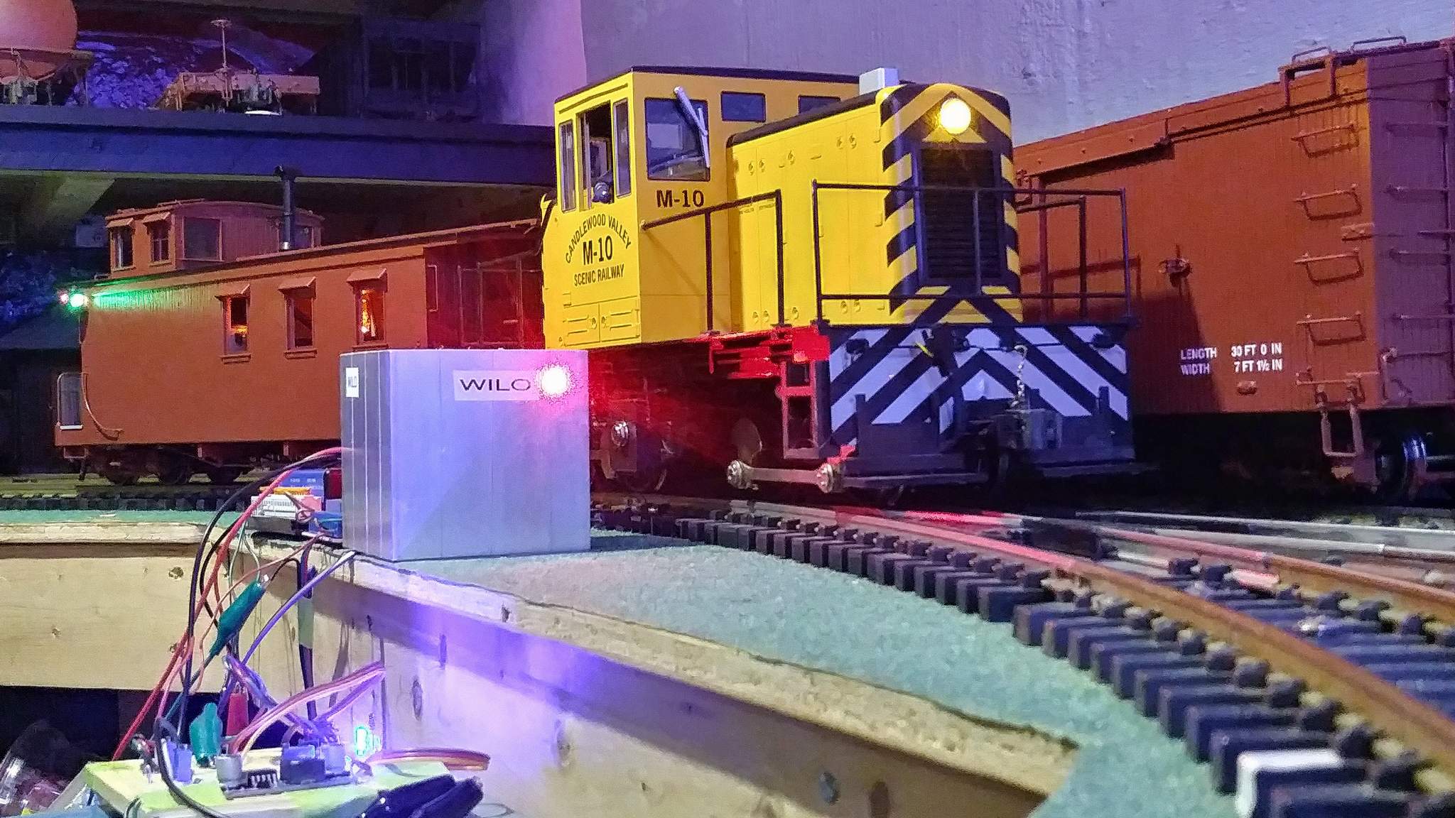
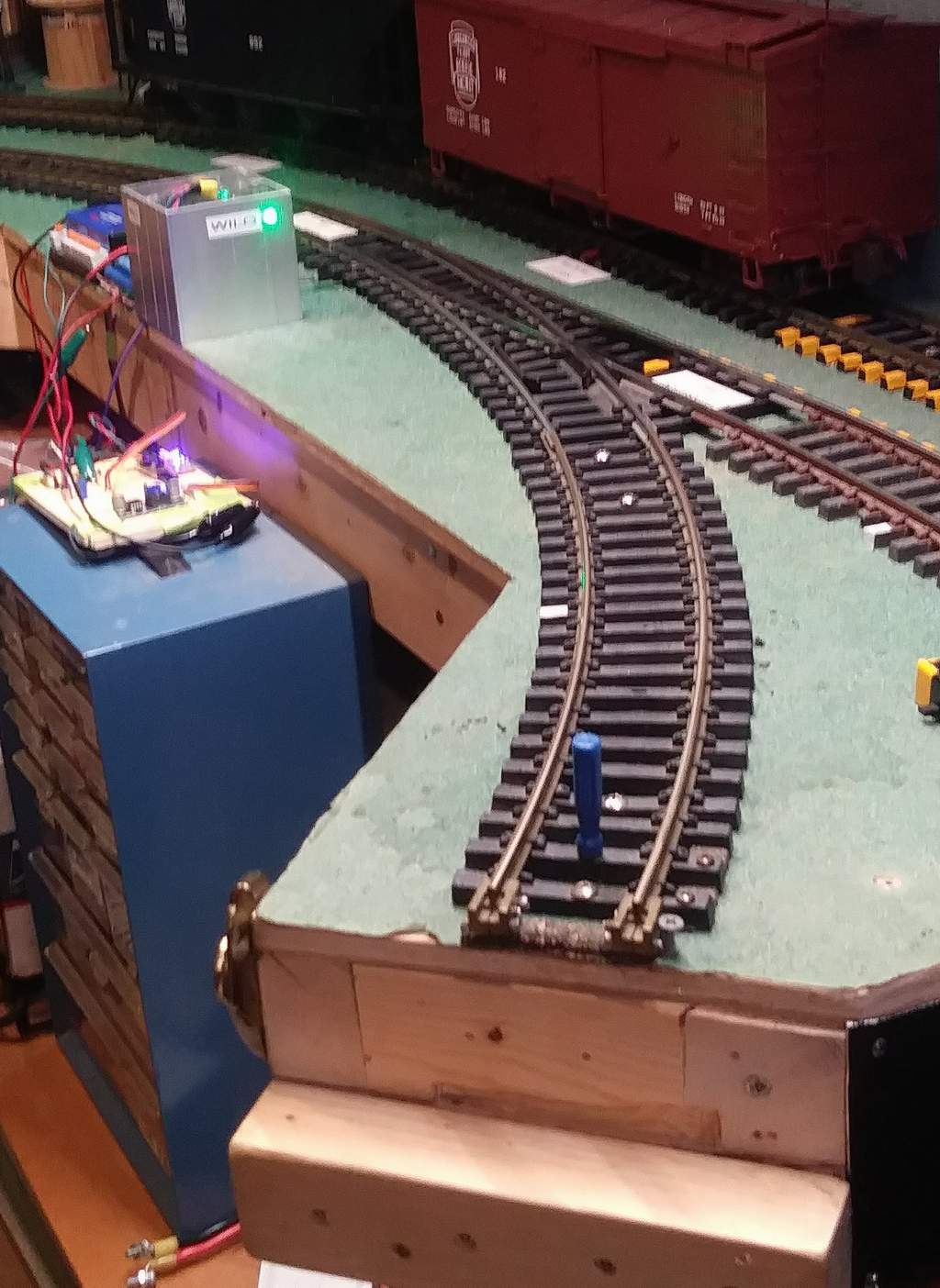
In the photo, the relay module is at the top, above the servo with an LED connected directly to the module. Not shown is a RailPro LM-3S-G which is temporarily being used to trigger the relay. The RailProc HC-2-SUN is at left. The second to last button on the bottom row controls the turnout. One photo for each position, Straight with Green LED indication and Curve with Red LED indication…

I’ve also done some fail-safe testing. The default power-on position of the Servo Tester is for the straight route. If I throw the turnout to the curve position, then power down the system, it will stay put so long as power is gone, but returns to the default straight route on power-up.

The last piece of the puzzle is the RailPro AM-1 accessory module, which I hope will be here soon.

As an exercise to learn a bit more about my upgraded version of Visio (I skipped 22 years of updates), I tried my hand at drawing what is working so far…

Jon Radder said:

As an exercise to learn a bit more about my upgraded version of Visio (I skipped 22 years of updates), I tried my hand at drawing what is working so far…

Looks good.

Could you used a DPST relay instead of a 2 x SPST relays with 1 pole switching the trimpot and the other switching the LED?

Only using 1 relay board input for 2 devices.

GAP said:

Looks good.

Could you used a DPST relay instead of a 2 x SPST relays with 1 pole switching the trimpot and the other switching the LED?

Only using 1 relay board input for 2 devices.

Yes, I absolutely could. I am only doing 2 turnouts in close proximity. Relay boards with 4 SPDT relays were dirt cheap, 2 DPDT relay boards were three times the price! So, it was a financial decision!

Jon Radder said:

GAP said:

Looks good.

Could you used a DPST relay instead of a 2 x SPST relays with 1 pole switching the trimpot and the other switching the LED?

Only using 1 relay board input for 2 devices.

Yes, I absolutely could. I am only doing 2 turnouts in close proximity. Relay boards with 4 SPDT relays were dirt cheap, 2 DPDT relay boards were three times the price! So, it was a financial decision!

Ah a man after my own heart when it comes to spending money I am very thrifty (wife calls me cheapskate)

I installed one servo tester, wired it up to the 5V the bus and mounted a switch to the control panel.
Next I installed a servo next to a point and connected it to the tester.
Following that I connected the servo horn to the point throwbar via a control rod with a clevis pin at one end, on the other end of the control rod at the horn I put a “Linkage Stopper” (these are used by the model aircraft people quite extensively).
The stopper has a grub screw adjustment so when I set the servo travel extremities using the 2 pots I could make fine adjustments to relieve any residual tension being applied to the control rod.
As the point I started with was on a crossover, I attached another servo to the other point and connected it to one of the tester outputs (there are 3) and now both points change at the same time controlled from the one control panel switch.
Now that I have it all working I will proceed with installing the rest of the servos to my points (12 of them).

The servos I am using are waterproof and are mounted under the baseboard.
I ran my irrigation sprays that are under the baseboard and no sign of any part being wet.
We also had 4 days of heavy rain and no water got under the baseboard everything was dry.
I am going to put a smear of silicone grease around the servo shaft to increase water repellence around its entry point.

I am using double walled heatshrink with a glue inside to keep moisture out of wiring joints.

Picture of the control rod showing the clevis pin and the linkage stopper.

Merged_document (1).jpg

Looking good! My project has stalled in the breadboard stage. Weather got better and my attention turned to finishing repairs on my RV so we can go camping soon. I did order a RailPro AM-1 accessory module from Don Sweet that will be here early next month. I’ll keep the breadboard setup while I work out the interface.

I do like your linkage ideas. Much better that trying the bend brass to exactly the right length! I bought a bunch of clevises and other push rod parts when my local Hobbytown closed up, so I should have everything in-stock to follow your lead.

I have published a page on my blog which shows the whole install of the servo controlled points, it contains links to the original article and the components used.

https://ringbalin-light-railway.blogspot.com/p/servo-controlled-points.html

GAP - In your blog post you mention that some of the testers worked differently. Did they all come in the same order from the same source?

Jon Radder said:

GAP - In your blog post you mention that some of the testers worked differently. Did they all come in the same order from the same source?

Yes they did; the only way to physically tell the difference was by the colour of the circuit board, the other way was at power up with a servo connected it moved the servo to the travel extremities before settling at the point where the control knob set the position.

Just to add to my last post;

By using the linkage stoppers and loose connection of the clevis pins the full extremity travel can be overcome, the servo just moves to the limits and then settles at the default point because the linkage allows it to travel over centre without applying excess pressure on the throwbar.

Hope that makes sense.

GAP said:

Hope that makes sense.

It does, but that sounds like you would need to do that every time the system is powered up. I know you are using a solar charged battery, but there is always a chance that battery will go flat. In my case, I’m using a power supply powered by house voltage and our power drops out fairly often. That’s why part of my design criteria was for the points to return to main-line route on power-up, even if the diverging route was selected when the power dropped out.

Jon Radder said:

GAP said:

Hope that makes sense.

It does, but that sounds like you would need to do that every time the system is powered up. I know you are using a solar charged battery, but there is always a chance that battery will go flat. In my case, I’m using a power supply powered by house voltage and our power drops out fairly often. That’s why part of my design criteria was for the points to return to main-line route on power-up, even if the diverging route was selected when the power dropped out.

Jon,

The tester goes through a self test at power up as part of its programming (I can’t change that), if it is powered only once then there is no self test ever again.

While it is performing the self test the linkage stoppers and the sideways travel of the clevis in the throwbar slot allow it to go through the motion without damaging the throwbar or the control rod.

If power is removed then once it is re applied the tester would go through the self test regime, the stoppers etc allow this to happen safely.

I am not using that type of tester on my layout so it is not an issue for me at this point in time.

I am just pointing out that it may happen depending on what is delivered and I may have to face the issue if I increase the number of testers in the future and end up with the self test version.

My default is also for mainline route.

Hi all,

I designed/built a 16 channel PWM servo controller and servo based turnout motors shown here.

Steve

A rainy and cold holiday weekend here, so I had some time to play with this project again. I picked up a RailPro AM-1 accessory module from Don Sweet and reconfigured it from a turnout controller that only supports snap or tortoise switches to a generic Accessory controller that has multiple on/off and a few motor outputs. Programming is pretty simple, so I set it up for two on/off outputs that drive the relay board I used in the breadboard system. All the electronics are still in breadboard stage, but the mechanics for one switch have been installed and tested extensively today.

I decided early on to recess the body of the servo in the bench. It turns out two holes bored close with a 3/4" hole saw then opened/squared up with a file or jig saw fit the servo perfectly. If only I had looked for framing under the plywood before I started boring! No problem, just open the hole longer and support one end with a styrene patch…

Like GAP - I used RC clevis ends and some threaded rod to make the push rods. A lazy S-Bend in the rod helps it align better…

Eventually some of the electronics and a pair or RGB LEDs will go into an aluminum equipment shed that will hide the servo while the LEDs indicate the switch position.

The next hurdle is learning enough of Eagle to create a board for the trimmers and send that out to be printed. If I knew exactly what IC was being used on the servo testers it would be great to build everything on one board, but for Version 1, the servo testers will remain a part of the system.

Today I started working on the modeling aspect of this project. The servos will be hidden by a generic “equipment cabinet”. Years ago I trimmed some 3.5" square aluminum post scraps to 3.5" cubes with this use in mind. Today, they were finally put to use. Looking at prototype photos for ideas, most of the aluminum ones are made from panels, so I scribbed in some vertical lines with 4 passes of a utility knife. I would really like the lines to be wider and deeper, but couldn’t come up with a better way with the tools I have. The cabinets were drilled for 5mm LED holders and an opening was made for the push rod. Here is the preliminary test placement…

I’ve not worked out what I am going to do for a roof. Simplest would be a piece of flat aluminum stock attached with screws to the C shaped extrusion. The prototype I looked at has a slightly pitched center peak roof. I could bend something at work on the brake that might work. Cutting the end gables would be the challenge. That, and nearly all of the aluminum sheet stock I have at work is painted white or black. I suppose a black roof might work.

Next I soldered up a pair of RGB LEDs onto a multi conductor cable for the position indicators. These are wired to the relay board which has both N.O. and N.C. contacts for each relay. The default position (at power-up) is with the relay Open which sets the points to main-line and illuminates the green part of the LED. Shown here with M-10 doing the clearance test…

And another test with the switch thrown to the Willow Hill spur…

There is only one problem with the system defaulting to the main-line. The lift-out bridge just a foot or so away and might be open with just a manually placed peg being the only thing keeping a train from going into the abyss…

Fortunately, the RailPro system offers a solution. There are several inputs on the Accessory Module which can sense the position of an SPST switch. Their accessory programming logic allows for the state of an input to determine what action is (or is not) taken. I will be adding a SPST push button switch to the closure area of the bridge. I need to work out the exact program, but the theory is: If the bridge is down, allow the switch to be thrown to the main line. However, if the bridge is up, do not allow selection of the main line; move to and stay in the spur position until the bridge is down. I just need to work out and test the logic.

Another potential use for an input would be to sense a fascia mounted toggle switch used to throw the points if the hand controller isn’t handy. The logic for that might be a little tricky since it’s position will need to be ignored when the hand controller is used to throw the switch. Logic for this functionality is a bit hazy at the moment (https://www.largescalecentral.com/externals/tinymce/plugins/emoticons/img/smiley-surprised.gif)so it will be a future enhancement.

Just when I had all the logic figured out and was just waiting on some Common Anode RGB LED’s so I could eliminate using the second relay to switch the LED’s and support Green/Blue alternating LEDs when the bridge was up - My new RailPro AM-1b crapped the bed. I’m pretty sure I didn’t overload it. Was diving a total of 300mA of bulbs with only one lit at a time when it threw an internal short circuit protection fault and shut down forever. The AM-1b will support a total of 400mA of load; either all on one output or divided among all the outputs.

By the time I get it repaired and back I’ll be well into summer stuff, so it looks like this project is DOA until fall (https://www.largescalecentral.com/externals/tinymce/plugins/emoticons/img/smiley-frown.gif)

That’s unfortunate! Any way to find out what happened? It would be bad to get it all fixed only to have it happen again.

I talked to the owner of Ring Engineering today. I may have F’d it up myself experimenting with using the negative side of a motor output as a switched Logic LO signal as referenced to the +5V output. I was told that’s a no-no, but he was surprised the built-in overload protection didn’t catch it.

Anyway, he says it can be fixed or replaced for $30 if it was my doing or free if he finds a defect. Just waiting for an RMA email so I can ship it.

So, I guess I’m going to end up paying some stupid tax. Ring says the board had a power output directly shorted to an input. I don’t recall ever making a direct connection, but I was playing with LEDs and Bulbs looking at all the inputs and outputs so I really can’t argue. To make it not hurt so much, they are allowing me to trade the fried one on a new one with sound. I’ll be more careful next time!