Perhaps I missed it, but I don’t think so as I went through the thread twice.
What kind of wood are you using, Bob? It looks like cedar did I get the brass ring?
Perhaps I missed it, but I don’t think so as I went through the thread twice.
What kind of wood are you using, Bob? It looks like cedar did I get the brass ring?
Steve,
Yes, you win the prize. The wood is western red cedar.
Pete,
The spikes are 3/8" medium spikes from Micro Engineering. Link: ME Products Listing
P/N 30-104 is a small package of 800 and P/N 30-103 is a bulk bag of 12,000. I buy them in the larger bags. This particular trestle will need well over 4,000 spikes by the time I am finished.
I use a tool called “The Spiker” from SwitchCrafters for all of my hand-laid track and switches. P/N is TS375. I know that he is no longer making switches, but the web site is still active and he may still have the tool in stock. Link: “The Spiker” Product Page
Bob
Bob Hyman said:
Steve,
Yes, you win the prize. The wood is western red cedar.
Dang…missed another one…(http://www.largescalecentral.com/externals/tinymce/plugins/emoticons/img/smiley-foot-in-mouth.gif)
Bruce Chandler said:
Bob Hyman said:
Steve,
Yes, you win the prize. The wood is western red cedar.
Dang…missed another one…(http://www.largescalecentral.com/externals/tinymce/plugins/emoticons/img/smiley-foot-in-mouth.gif)
Someday you will be a bride ! For now we are just maids.
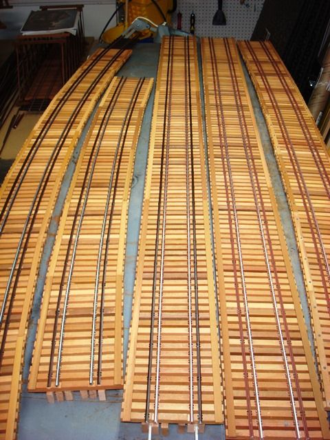
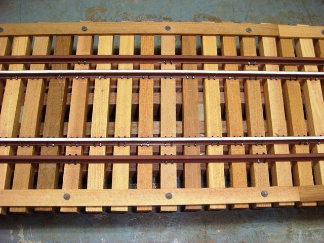
Finally finished spiking all the rails on all five segments. I also added the guard timbers along the tie ends. Here are all five segments setting on the workbench. You may notice that I shortened segment #4 by 32 scale feet, bringing the total trestle length down to 528 feet and the number of bents down to 34. This was to accommodate adding a curved switch immediately after the end of the trestle.
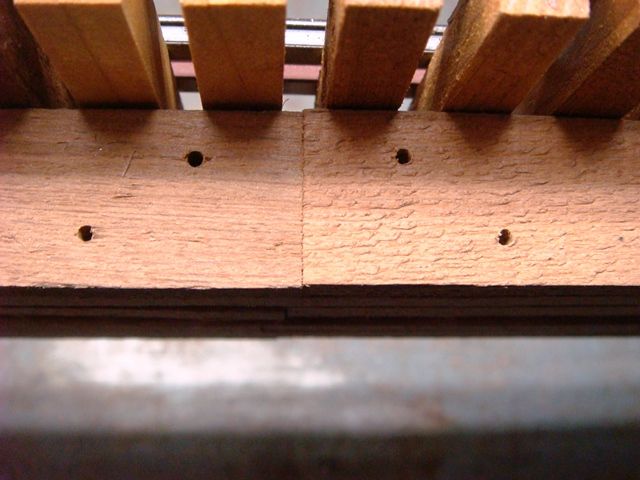
I drilled 1/16” diameter holes in the stringers at each bent location.
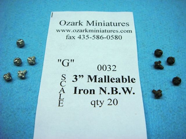
I pickled the N-B-W castings in a commercial brass blackening solution. Here is how they looked before and after.
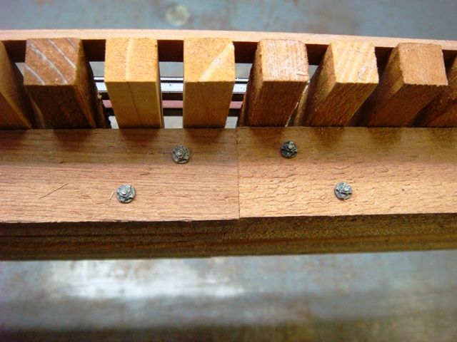
Here is how they look installed.
After I installed all of the N-B-W castings on the stringers, I added some different N-B-W castings to the guard timbers. Here is how they look.
Next, I will start adding the bents to the deck. In the next installment, I will show you how I keep the bents perfectly vertical when the deck is inclined on a 2½% grade.
More to come,
Bob
WoW … . what a fantastic project ! 
Wow…(http://www.largescalecentral.com/externals/tinymce/plugins/emoticons/img/smiley-cool.gif) Nice work…
Great work Bob, that’s going to be a beauty. Thanks for posting.
Chuck
What they all said… Looks great… (http://www.largescalecentral.com/externals/tinymce/plugins/emoticons/img/smiley-cool.gif)
Today we’re going to figure out how to set the vertical bents under a deck that is not horizontal. If the track across the bridge were horizontal and perfectly level, then the vertical bents would be at a 90 degree right angle, or perpendicular to the deck. However, if the track is inclined on a grade, then the bents must be at some angle other than 90 degrees to the deck. Here is a representation of the problem. You can see that on the inclined deck, the angle between the deck and the bent is slightly greater than 90 degrees on the uphill side, and slightly less than 90 degrees on the downhill side.

We generally know how steep our grades are and express the gradient in terms of percent. That is simply rise over run. If the track climbs 2.5 units in 100 units, then the grade is 2.5 divided by 100, or 0.025, or 2½%. But how can we convert that grade into the proper angle to set the bents?
Okay … snug up your seatbelts because it’s about to get a bit bumpy. At least for any normal person who doesn’t know or care about trig functions. Trigonometry is an old Greek word that means “one who cannot play football.”
There just happens to be a trig function that will give us the proper angle for the bent. It is the inverse sine, sometimes represented as asin, or arcsin, or sin-1, depending on your calculator. The inverse sine of the grade is the angle of the inclined deck. The inverse sine of 0.025 is 1.4325 degrees. This means that the deck is inclined 1.4325 degrees from horizontal. The bents attach to the deck at 90 degrees plus or minus this angle. If you measured the angle between the deck and the bent on the uphill side, it would be 91.4325 degrees. Measured on the downhill side of the bent, the angle would be 88.5675 degrees.
Captain just turned off the seatbelt sign, so you can relax from here on out.
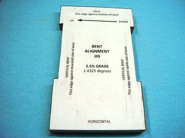
We’re simply going to take this abstract mathematical function and turn it into a tool that can be used without worrying about the math. Here is a paper template for a bent alignment jig for a trestle on a 2½% grade. I drew a rectangle and angled the top at 1.4325 degrees. I drew in notches on each side to fit around the diagonal braces.

I printed out the template and glued it to a block of ½” thick medium density fiberboard (MDF) slightly larger than the template and sanded the edges right up to the lines. I cut out the notches with a scroll saw. Here is the finished jig.
The jig serves two purposes. First it is used to set the angle for sanding the top caps of the bents. Here it is being used to set the proper angle on the disk sander. Later the jig will be used to position the bent against the deck.
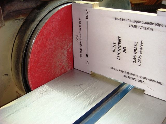
The top cap of each bent is then sanded to this angle. Note: It is easier to sand the bent tops before the
diagonal braces are added.
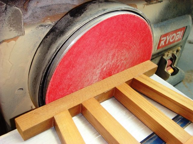
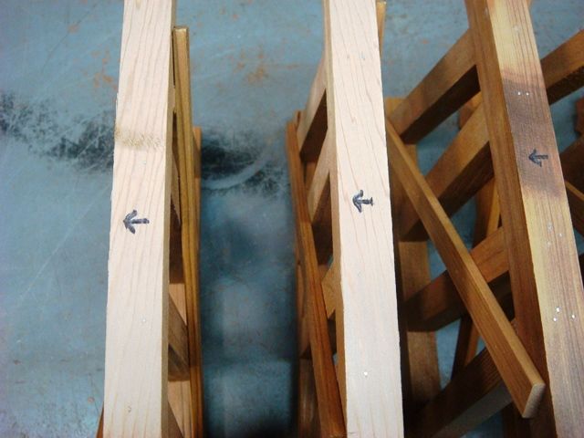
After the bent caps are sanded, one side will be a slightly bit higher than the other. Mark each bent cap with an arrow pointing to the higher side. When we install the bents, the arrow will point in the uphill direction.
Position the bents using the bent alignment jig.

I glue each bent cap to the stringers and tack it in place with four 1” long 23 gauge pin nails. Here is the underside of Segment #1.
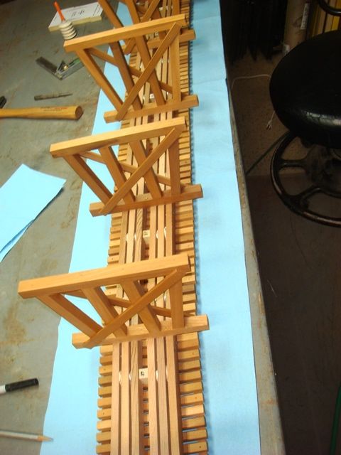
And here it is right side up, ready to install.
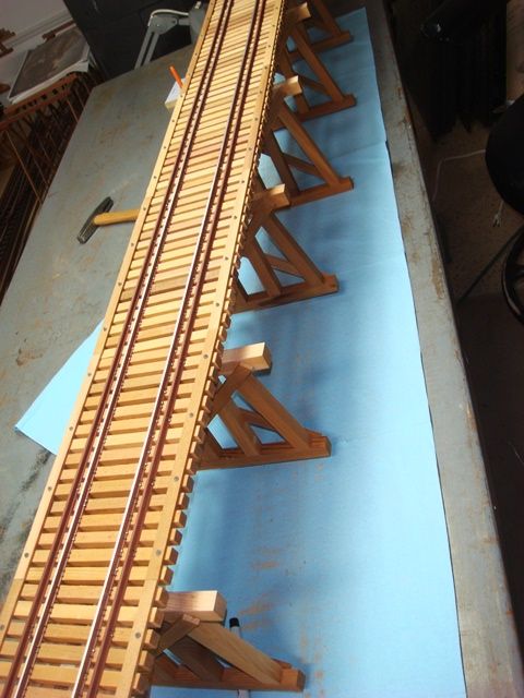
I’ll continue placing the bents on the other four segments as time permits. After the holidays are over, and the weather improves, I’ll start on the concrete foundations and we’ll get this monster “planted”.
More to come,
Bob
Well, good, since you have it all figgered out, any trestle I need with a 2 1/2% grade, you’re hired…(http://www.largescalecentral.com/externals/tinymce/plugins/emoticons/img/smiley-wink.gif)
Fantastic . . . .
Is this going into a museum ?
Very precise … not on my pike!
Love the updates Bob!
maybe, it is the language barreer, but i’m not sure, if i got it.
did you make the trestle bents standard, like all others, and just filed the upper beam to angle?
Korm Kormsen said:
maybe, it is the language barreer, but i’m not sure, if i got it.
did you make the trestle bents standard, like all others, and just filed the upper beam to angle?
That’s what I got out of it Korm, but I didn’t finish trig in school(http://largescalecentral.com/externals/tinymce/plugins/emoticons/img/smiley-cool.gif)
Bob really needs to get himself a hobby!
I want to retire!
Gee, I just eyeball it.
When Rooster does that, does it come out cock-eyed?
Oh my…
Oh yeah, really nice build!
John
Gee, I am cornfused.
I don’t know trig. But I do know that an incline at 45 degrees is at 100 % grade. So, dividing 45 degrees by 100 percents tells me that each percent of grade would be .45 degrees. 2.5 percent grade times .45 degrees per percent would be 1.125 degrees, so the bents would, with my messed up math, join the stringers at 1.125 degrees off of 90.
So, its a darn good thing you didn’t let me figure that one out.
David,
An incline of 45 degrees is not a 100% grade. Consider the following example:

With a 45 degree incline, the run is 1.414 units for every 1 unit of rise. Since grade is rise divided by run, the grade is 1 divided by 1.414, or 0.7071, or 70.7%.
Bob
Wow somewhere on this page the language changed to something I couldn’t understand, I was interested in this but now this language barrier has lost me. LOL. Are you going to charge us to print out copies of your jig? Great work and thanks for doing the grunt work, I would have had to get my son in law over to figure this out for me. Keep it coming, awesome work.