Large Scale Central

Front pilot is coming off track, need help!

I actually was able to fit lead under the pilot truck of this loco a number of years ago when the pilot wheels were coming off the track and that definitely made a difference. I’ve also tried to stretch the spring under the pilot truck but that does not seem to have made any difference.

There is one thing here that I did not mention and don’t know if it makes any difference. However, just prior to this all happening, the rubber traction wheel on one of the drivers snapped and broke apart. I do notice that the loco wobbles more side to side as it is moving down the track. Is it possible that without the traction wheel the loco is having issues going through the switch? It’s only the switch on the left reverse loop that is showing issues.

I’ve checked and cleaned the switch throwbar and mechanism and that has not made any difference. I can gently push the loco through the switch with no issue, the pilot does not come off the track. I haven’t tried to work with the actual spring within the switch yet. I will try that.
It’s probably waddling more side to side than usual. The groove for the traction tire could cause tracking problems I would guess, but your issue is before the driver, it’s the light pilot with a lot of play and little downforce that cannot do it’s job.

A rocking of the loco side to side might be able to make this worse I guess.

Also, check that under power, the front of the loco is not lifting, putting even less down pressure on the pilot.

Greg

Well, if the traction tyre is missing, the locomotive will waddle, and wobble and all that motion can cause issues. I would fix the known problems (missing traction tyre) before trying to solve the unknown problem (why it’s derailing). Many times in my work, 2 seemingly unrelated issues with a piece of equipment, are in fact related. Solving the simple problems quite often solves the more complicated one, or at lest it gives me a start on solving it, because I am not chasing 2 problems at once.

As I mentioned earlier, after cleaning the switches and filing down a very small notch on the left track of the switch I was able to run the Christmas consist for a few hours on Christmas day before the issue started happening again. I do plan on replacing the traction tire that snapped and fell off on the chance that it may have added to the issue of the pilot wheels coming off the track when going through the one switch (it doesn’t happen on the other switch). At least it will keep the loco from wobbling back and forth along the track.

So I’ve decided that next year I would try to wire up the switches to switch automatically instead of depending on the spring loaded approach. I’ve been using the VCS Magic Motorman for this layout since 2004 with the switches being spring loaded with no issues (or minimal issues).

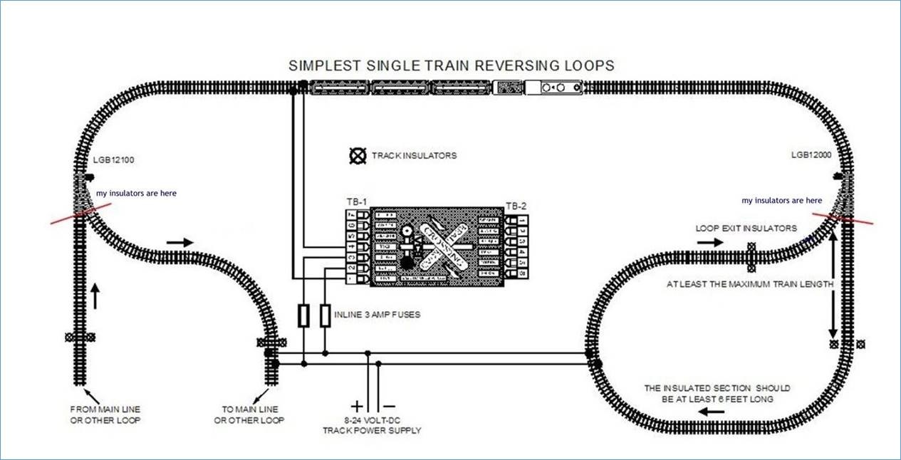
Here is a diagram of my current simple configuration with spring loaded switches and the VCS Magic Motorman (no longer made):
http://redmondcreekrr.timothydehan.com/web/simple.jpg

Simple Loop

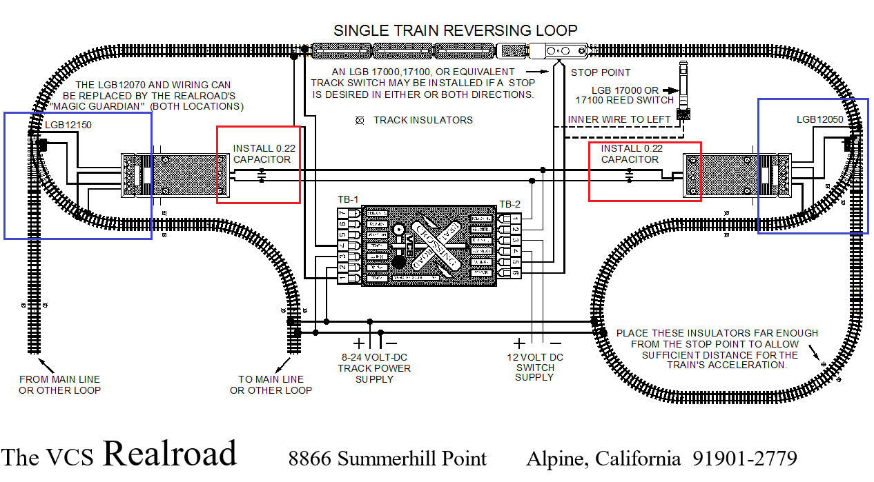
Here is a diagram of the Magic Motorman with wired switches. It also includes the wiring if I want to add a station stop which I don’t. So I’m ingorning that part. I have 2 of the LGB 12010 switch motors and the LGB 12070’s. If I am reading the diagram below correctly it appears that both of the LGB 12010 switches are wired to the track in 2 locations (see blue outlines). Which seems odd to me and I’m not clear why that would be. I am also not clear about the part that says “install 0.22 capacitor” (see red outlines). Not clear what the capacitors would be for or exactly how they would be wired up based on the diagram. As mentioned, the Magic Motorman is no longer made. Any thoughts anyone would have would be greatly appreciated.
http://redmondcreekrr.timothydehan.com/web/MagicMotorman_Large.png

wired switches

They are connected across the contacts to the switch motors. 0.22 Mfd disc capacitors 50v would be fine. They help eliminate noise caused by the long leads to the switch motors. Probably work without it for your testing.

Ok, thanks Greg.

It also appears from the second diagram that there is an additional insulated section (if I am reading the diagram correctly). Presently on the Simple Loop diagram there is an isolated section in each loop that remains a constant polarity. In the second diagram it appears to have an additional insolated section after that has connections from the switch motor to the track? Am I reading that right? If that is the case that section does not appear to have any power.

In the second diagram there are 3 separate power sections, the left loop (somewhere those 2 tracks need to be connected together), the right loop, and the middle. This allows the station stop.

On the left 2 tracks, yes the far track on the left has no power, but read the descriptions at the “ends” of those 2 tracks, it says you either complete the loop or connect to the mainline… so the left 2 tracks that appear to end actually are connected together somewhere so the leftmost track gets power from the one to the right of it.

If you make the track plan EXACTLY as shown, you would connect those 2 tracks together to make sure both are powered.

Greg

Hmmmm… that doesn’t seem quite right or I’m not understanding.

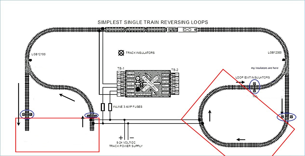
I’ve edited the diagram of my current setup using the spring loaded switches. The mainline and each of the loops are wired left rail HOT. The locomotive starts in the middle of the mainline and travels LEFT. The locomotive always enters and travels through each of the loops as indicated by the arrows. The insulators in each loop are circled in BLUE. The RED boxes indicate the the insulated loop sections. When the locomotive is within the insulated loop sections the Magic Motorman switches the polarity and the locomotive smoothly exits the insulated loops and back onto the mainline headed for the opposite loop.

http://redmondcreekrr.timothydehan.com/web/simple2.jpg

Simple Loop

I’ve edited the second diagram with the automatic switches to make it cleaner. As with the simple loop, the mainline is wired left rail HOT as are the insulated loop sections on either side. The Locomotive always starts on the mainline and moves left. The Locomotive always enters the loops each time in the direction indicated by the arrows. The red boxes show the current layout of the insulated loop sections. When the locomotive is within the insulated loop sections the Magic Motorman switches the polarity so that it exits the insulated sections smoothly and travels back onto the mainline in the direction of the opposite insulated loop.

The question here is that the diagram shows additional insulaters (highlighted in PINK) after the current insulated section which would then be another insulated section (highlighted in YELLOW). However, that yellow section according to the diagram has no power. My guess is that this additional yellow section and pink insulators are a mistake?

The next question is, it appears according to this diagram that the track switches require their own separate power source?

http://redmondcreekrr.timothydehan.com/web/MagicMotormanSingleTrainReverseLoop.JPG

I see, did not look for additional insulated sections in the second diagram… yes not powered, clearly a mistake.

OK, back to the beginning… so the first diagram, january 10 post, I do not see how this operates unless the magic motorman senses a short circuit and reverses the main line when exiting the loop… also it seems that in the first diagram, you must always enter each switch in a particular direction.

Correct so far?

Greg

Correct. As mentioned in my last post, the Magic Motorman switches the polarity once the loco is within the insulated loop section so that it can exit smoothly back onto the mainline moving toward the opposite loop where the process happens again.

Correct, the locomotive enters each of the loops the exact same way each time. The arrows in the updated diagrams show this.

The data point I wanted was the mechanism how the unit knows to switch polarity. looking at that first diagram, if it is correct, then the unit MUST sense a short circuit and reverse, there are no other detection mechanisms.

Can you confirm this is how it operates? Is there a manual I can get? Is this particular item documented in the manual?

Just want a firm foundation to go forwards on, those 3 questions answered will help.

Greg

Unfortunately since the item is no longer manufactured and their website is no longer around, there is not much detail regarding how the item works. But this is how I understand it.

The Magic Motorman initially sends out tests to see how the track is configured. It automatically detects where the insulated sections are as well as the mainline. When the power is first applied, there is a few seconds before the locomotive slowly starts to move as a results of these tests. According to the website, it stated that the best procedure is to have the train somewhere on the main line and not let it enter the reversing track for at least 15 seconds after power is applied. Even though I typically start the train in the middle of the mainline there have been times when I have started it closer to the first (left) loop and there is less than 15 seconds prior to entering the loop with no issues. The instructions also stated that upon the initial trip around the track the Magic Motorman will measure the distance between the sections and make tests along the way to observe how the track is configured.

So, yes the unit does know there would be s short circuit and reverses the polarity while the locomotive is within the insulated loop sections (where the polarity is always constant, left rail HOT). There are no other detection methods.

AH HAH!

Those are not insulators, those “extra insulators” are LGB switch contacts…

Where did you get that picture, seems someone has removed important descriptive text:

Are you asking me where I got the pictures? If you are asking me where I got the pictures I posted above, they came with the Magic Motorman when I purchased it.

the picture you are showing here I’ve seen before but believe it was the diagram used to show how to wire up the reversing polarity using simply the LGB switch motor and reed switches. Where did you find that picture?

I found the document that came with the Magic Motorman, http://redmondcreekrr.timothydehan.com/web/motorman.pdf

Timmy, I’m an old fart, but I do have my ways ha ha!

Yes I see that same illustration in the document and it is clearly in error…

On the left side, that insulated section serves no purpose as it is drawn, I think someone copied the picture I had and put insulators where the LGB contacts were.

Since power flows through LGB turnouts, the wires from the switch machine on the left will cause a short at one position of the switch machine.

The upper 2 wires, that are just “north” of the points can stay, but the other 2 should move “south” to the insulated section.

That should fix it.

Greg

HAHAHA… yes… we are all getting older Greg. Thanks for all your input here. I need some clarification from your last post.

You state that the left side insulated section servers no purpose. I assume you are referring to the pink/yellow part of my diagram? If that is the case then the same would hold true for the right side loop as well?

You mention that since power flows through the LGB turnouts, the wires from the switch machine on the left will cause a short at one position of the switch machine. This I assume throws the switch itself as it has nothing to do with the switch in polarity which is managed by the Magic Motorman solely. If you are indeed referring to the short throwing the switch then again I assume the same is true for the switch on the right side loop.

Also, I believe the throwing of the switches is done solely by the brain within the Magic Motorman. I do not believe any reed switches (LGB 17000) are needed to perform this task. The diagram that came with the Magic Motorman mentions the LGB reed switches in the event a station stop is desired.

Timmy

Your diagram is missing something.

Those “insulated” pieces of track are not completely insulated. They are connected to the adjoining track with an LGB 10153 or insulator installed on the left rail in the direction of travel with a diode installed across the insulator. (http://largescalecentral.com/externals/tinymce/plugins/emoticons/img/smiley-wink.gif)

Yep and Yep.

So my guess is someone copied a diagram, confused the insulator marks with the other similar marks for the LGB contact switch, used to do automatic operation of the turnouts themselves.

Power flows “through” LGB turnouts, the position of the turnout does not direct or stop power to the 2 routes “out” of the turnout.

The contacts that go to the track are used to power sections “beyond” the switches, and the wrong polarity will cause a short circuit on the left side since the “switched power” is applied to the track that is NOT isolated, i.e. not in the yellow, where you can set either polarity (since it is an insulated section)

The switch contacts are taking the power from just before the points and applying it past the points, where power is ALREADY.

Ahh, I was assuming it was reversing the polarity, but maybe those contacts are just supplying power… if that is true, then it will either never do anything or always short.

What are those contacts in the LGB switch machine, I need a schematic of them.

Greg

BTW, know that the Magic Motorman converts linear power to PCM and may not be compatible with some power supplies.