With most miter saws you have set locations …0 …22-1/2 … 45 … which helped me decide the angles … (https://www.largescalecentral.com/externals/tinymce/plugins/emoticons/img/smiley-wink.gif)
Devon,
Here is a timber Howe Truss bridge I built from a Smith Pond Junction kit. link to kit
I know that SPJ is closing shop, but some items may still be available.
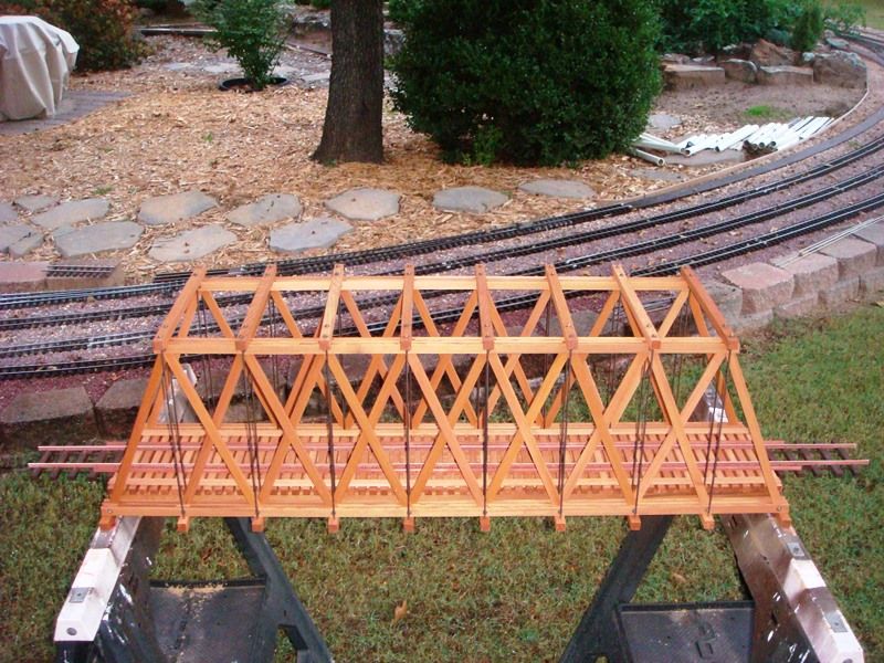
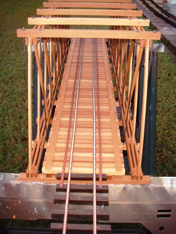
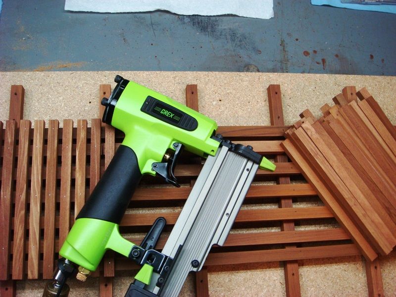
I used the basic kit plus a 12" expansion kit to create this 36" long span. I used a brass blackener solution to darken the threaded brass rods that keep the beams in tension. I cut the bridge ties from cedar and nailed them to the lower beams with 23 gauge pin nails. Rail is code 215 aluminum spiked to the ties with 3/8" spikes from Micro Engineering.
Although it is not a prototypical design, it does give the overall impression of a Howe Truss. The bridge is very strong and supports anything I want to run across it. I believe you can purchase the plans separately if you want to cut your own timbers. Also, I think the threaded brass rods are available separately.
Bob
Hey … I used that for my trestle build…
Bob Hyman said:
Devon,
Here is a timber Howe Truss bridge I built from a Smith Pond Junction kit. link to kit
I know that SPJ is closing shop, but some items may still be available.
I used the basic kit plus a 24" expansion kit to create this 48" long span. I used a brass blackener solution to darken the threaded brass rods that keep the beams in tension. I cut the bridge ties from cedar and nailed them to the lower beams with 23 gauge pin nails. Rail is code 215 aluminum spiked to the ties with 3/8" spikes from Micro Engineering.
Although it is not a prototypical design, it does give the overall impression of a Howe Truss. The bridge is very strong and supports anything I want to run across it. I believe you can purchase the plans separately if you want to cut your own timbers. Also, I think the threaded brass rods are available separately.
Bob
Bob,
I am thinking for simplicity and looks this is a great design and I very well might just build mine like this. Along with what everyone else has shared here I am thinking I can come up with a solid workable design that only I will know is not prototypical. I mean that bridge looks great and that is the most important part.
M+3=2N
The thing with that design, and it is very similar to Korm’s, is I can wing it. The angles don’t really need to be engineered as much as just deciding where the cross members should go and then marking them so they are flush then setting the saw to cut whatever angle that is. It can be designed more for aesthetics than having to be exacting, unlike trying to match blocks on a traditional Howe. Add in boomers pipes or some other support and a bridge like that would be bullet proof.
To have a stable truss design that is statically determinant, you must conform to the formula above.
M=# of members
N=# of nodes (connections between members)
The length of each “bay” needs to be equal to or less than (preferable) the height. In your case:
Height = 12”
Length = 35”
35/12=2.92 bays
so, if you chose 3 bays, the length of each one would be 11.67”
4 Bays=8.75”, etc, etc.
I think an odd number of bays looks better from a symmetrical standpoint. Remember, the two angled bays on each end each count as a whole bay when calculating the length of each bay. Clear as mud, right?
Dan it might take a while to absorb what it is you posted there. I will have to dwell on it but thanks that is exactly the type of thing I was after. I knew there had to be a formula to figuring out what I needed.
looking at the bridge of Bob’s; what are we calling “bays”? I am assuming the area between each vertical rod is a bay and the ends are still considered one bay each. So Bob’s bridge is 9 bays?
I have built a few basic howe truss type bridges for my RR and I winged it.
Start with the length of the base you need then the height, I would recommend at least 10" from the rail head. Using a 45 degree angle is probably the easiest to work with but if you want more beams and cross members then go for it but the angle will have to be sharper. Build the upright beams parts first by making a square frame then space those evenly out along your stringers (the length of your bridge) nail in place then add the diagonal supports cutting the angles that you need.
Building bridges is fun.
Devon Sinsley said:
looking at the bridge of Bob’s; what are we calling “bays”? I am assuming the area between each vertical rod is a bay and the ends are still considered one bay each. So Bob’s bridge is 9 bays?
Yes, Devon, Bob’s bridge has 9 bays by my definition.
Ken Brunt said:
Judging by the spans this one is 36".

I see it as 12" or 3 X 4"=12"
The 10.5625" under neath starting on the same line is the clue, should be the same scale horizontal as vert.
Can’t go wrong with welded steel but not sure it will fit your era
" Rooster " said:
Can’t go wrong with welded steel but not sure it will fit your era
No steel isn’t really an option both era and location/prototype. But I would like to build a true riveted steel bridge. Okay maybe soldered brass and fake rivets but I do think it would be fun to build.
Too bad about steel, whadda bout Iron?
this one is pinned links and cables…
Presenting the Fink Truss:

Wow that’s interesting. It looks exactly like the foreman had the plans upside down! (https://largescalecentral.com/externals/tinymce/plugins/emoticons/img/smiley-tongue-out.gif)
That would be fun to build
An old favorite …

