Large Scale Central

Hale & Norcross

No Cliffy…you are missing what i’m saying. But what would I expect from a Solidworks user who designs fun-rides and nothing serious. I guess I will have to draw you a picture. (I will make the words really big so you can see them.)

I can see what you are saying about the wind. Here we get plenty of that. I have been trying to think of an idea that would prevent me from needing access to nuts and bolts.

Chris Kieffer said:

… I guess I will have to draw you a picture. (I will make the words really big so you can see them.

Maybe that’s the bright side of having to use Crayola’s, but sure fire away!

For the record, I did my time with Pro-E, but years ago graduated to Solidworks.

Dos centavos, thanks Juan.

BSEG

(as we old farts used to say on Compuserve, back in the day)

Cliff,

Hahaha…I was going to drop the crayon joke on you!

Here is a sketchup quickie of what I was talking about. I understand what you are talking about with the concern of a crack starter, but this really won’t be a high movement application, so as long as you don’t crack them when putting it together, it should be fine. The reason I suggest this approach is that it backs up your chemical joint with a mechanical one. Even though you are using a solvent based adhesive (good idea btw) there is a chance of adhesive failure over time, mostly due to the elements. With this building being larger, it would be more susceptible to expansion / contraction weaking your bonds. I drew this with a hole for a #10, but I would think #8 would be sufficient. You can see even with the 3/16" hole, there would be about 1/2" to the edge. It would also reinforce your joint when you are moving the buildings. With the amount of work you are putting into these, I would hate to see a corner blow open on you and ruin your work.

Anyway, that is my two scents…sense?, since?, …my two useless coins.

Chris

Chris, that’s a nice diagram, thanks. I get what you’re saying; and with aluminum angle, one could match drill and it would be pretty easy.

Hmmm…did the pictures show up for you? I’m not seeing them now.

Chris

I’m still seeing them ok, thanks again Chris.

Speaking of Crayola, here’s the current plan on how the modules will be breaking up. Again, these would be sealed units, butting up against each other. However, I’d need holes between them to pass wires through, so maybe the main one gets PVC pipe stubs glued in, which stab into the 3 other modules. We’ll see.

[edit] I think I’ll change the break between red and green… I was going to overlap green’s roof over red’s, to permit a simpler wall structure between. But that valley should be parked between modules for drainage, so the module break line is now at the valley.

Cool … tecnicolor even… :slight_smile:

Thanks Sean. I’m trying to make it easy for… ok, never mind.

See Chris, I held back.

RBSEG <<< Since we don’t have emojis, I’m improvising. For youngun’s like Chris, this means “Really Big Poop Eating Grin.”

:smiley:

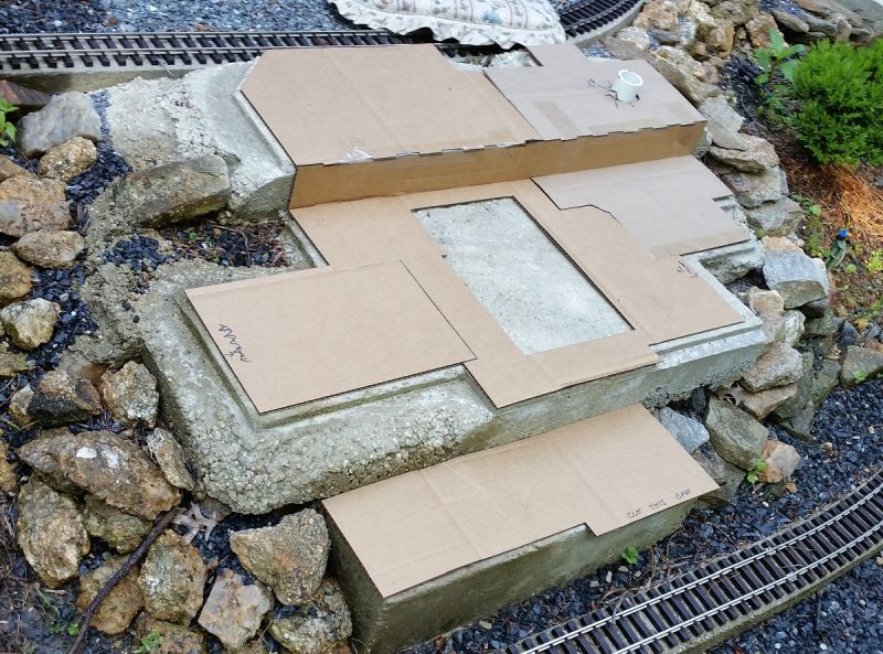
Here’s how the base sheets are working out.

The 1/2" gap all around is just for insurance’s sake. And there’s a 1/4" gap at the upper step, and around the lower step.

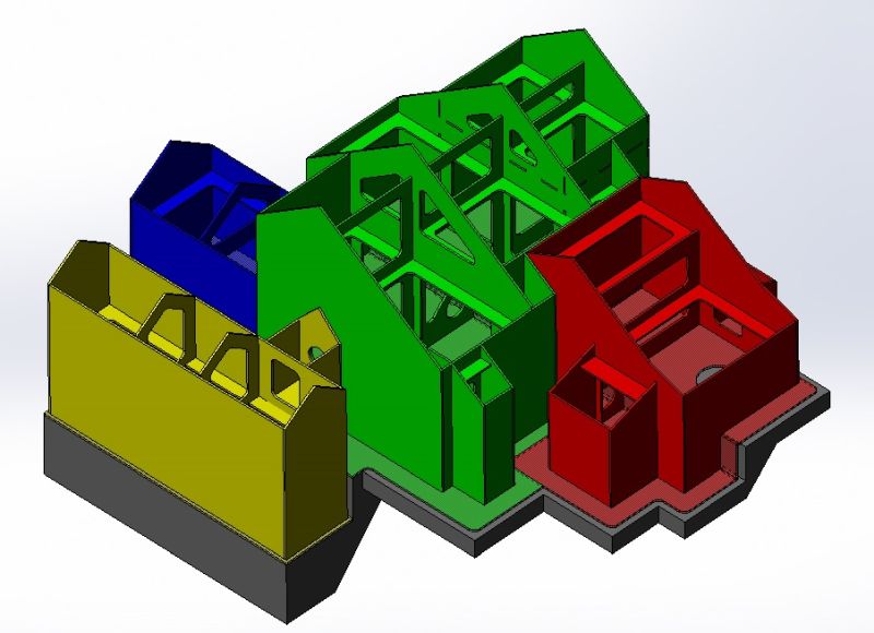
After other things affecting the base (walls, bracing) are in the model, I’ll need to laser these pieces early on to verify the geometry with the concrete, and adjust the model as needed. Hopefully they’ll still be useful as the module bases, but probably not after the adjustments.

But… if that’s the case, maybe cutting all this as a pattern in, say, masonite scraps, would be better. Have to see what sheet material is laying around. Hmm. If I do that, I should go line-to-line in the model with the 3d concrete, laser the pattern material for these pieces, set them out on the layout, manually mark or cut the pattern pieces to match the concrete, and adjust the 3D model from that before lasering any real parts.

Chris, would you concur?

Cliff Jennings said:

See Chris, I held back.

You didn’t hold back, your Alzheimer’s took over and you forgot what you were going to say. (http://largescalecentral.com/externals/tinymce/plugins/emoticons/img/smiley-tongue-out.gif)

I like your idea of the PVC stubs from the main to the sub modules. That would help with unintentional shifting between the pieces. Are you going to fasten part of the structure to your foundation?

Chris

Serious hacking and coughing LOL

Now I have someone to blame for my next stroke. :smiley:

I’d rather not make hard connections with the concrete, but (assuming the modules are fastened together), if I felt I had to due to wind vs. size of independent structure, here’s what I’d do (since you asked):

  • Cut or drill a 1/2" hole in the acrylic base

  • Hammer-drill a 5/16" hole in the concrete

  • Pound a plastic anchor into the concrete

  • Use a #10 pan head SS sheet metal screw, fender washer and rubber washer to secure the base to the concrete

However, that approach makes it tough to remove for the winter. So, maybe use a similar approach having a stud and wingnut above the base…?

Cliff get Threaded plastic pipe fittings and use them to screw 2 sections together, then you’ll also have wire conduits.

John; 67 going on 6, sez Sis.

If you think I’m going to cause you a stroke, you should see what I do to Jerry. I cost him so much he labeled me “The Enabler” He took to faking injuries just to prevent me from finding a trip he couldn’t resist. (http://largescalecentral.com/externals/tinymce/plugins/emoticons/img/smiley-sealed.gif)

Do you get high winds? I have to fasten my structures down because the Kansas “Breeze” will relocate them to my neighbors. But my layout will be elevated, so it will be easeir for me to do.

You ask if I have a suggestion:

So, enough of that nonesense, on to the suggestion: (Actual credit goes to Richard Smith and his Port Orford RR)

Those are Z Clips used for holding glass or mirrors, or even a glass mirror. You can get a large number of offsets from Home Depot or Lowes. I was thinking you could extend tabs from your bases outside the walls, then secure with these clips. Hide them with an accessory or gravel so they won’t be visible. Then when winter comes, loosen the screw and pivot it out of the way and your structure is free.

Chris

Chris Kieffer said:

If you think I’m going to cause you a stroke, you should see what I do to Jerry. I cost him so much he labeled me “The Enabler” He took to faking injuries just to prevent me from finding a trip he couldn’t resist. (http://largescalecentral.com/externals/tinymce/plugins/emoticons/img/smiley-sealed.gif)

Do you get high winds? I have to fasten my structures down because the Kansas “Breeze” will relocate them to my neighbors. But my layout will be elevated, so it will be easeir for me to do.

You ask if I have a suggestion:

You talk prettier then a 2 dollar…street walker

Oh look! spell checker and the emojis are back. (http://largescalecentral.com/externals/tinymce/plugins/emoticons/img/smiley-laughing.gif)

A $20 dollar one…which was a lot of money back then for one of those.

BTW, I slam dunked this weeks movie reference.

John Caughey said:

Cliff get Threaded plastic pipe fittings and use them to screw 2 sections together, then you’ll also have wire conduits.

John; 67 going on 6, sez Sis.

Good idea John. I was also thinking it would serve as the wire feed through, so it would need to pass a connector. So maybe a 1" bulkhead fitting:

https://www.plumbingsupply.com/bulkhead.html

But it would be cheaper to use a plastic 1" close nipple with 2 plastic pipe nuts and a couple rubber washers.

https://www.mcmaster.com/#4677t13/=1808z9a

https://www.mcmaster.com/#7945k83/=18090fs

https://www.mcmaster.com/#2610k65/=180918f

And Chris, good idea, good ol’ mirror clips. I like how they could swing away, like you mention.

Thanks guys!

To verify the base dimensions with the concrete, I did a quick pattern cut from cardboard. (A Harbor Freight box :wink: )

Couple of adjustments, but it basically fit. The concrete form patterns were developed from the same model, so I was glad to see that. It was good to see where the electrical stub-up was, that was only roughly placed in the 'crete.

Cliff Jennings said:

John Caughey said:

Cliff get Threaded plastic pipe fittings and use them to screw 2 sections together, then you’ll also have wire conduits.

John; 67 going on 6, sez Sis.

Good idea John. I was also thinking it would serve as the wire feed through, so it would need to pass a connector. So maybe a 1" bulkhead fitting:

https://www.plumbingsupply.com/bulkhead.html

But it would be cheaper to use a plastic 1" close nipple with 2 plastic pipe nuts and a couple rubber washers.

https://www.mcmaster.com/#4677t13/=1808z9a

https://www.mcmaster.com/#7945k83/=18090fs

https://www.mcmaster.com/#2610k65/=180918f

And Chris, good idea, good ol’ mirror clips. I like how they could swing away, like you mention.

Thanks guys!

Hey ol’ buddy, I’ve felt like I’ve had a hand in your layout from the beginning …

From experience; plastic pipe threads get ‘sticky’, I’d suggest a liberal application of graphite powder as your assembly goop.

I don’t think the graphite and the plastic will interact over the season.

Carry on. (http://www.largescalecentral.com/externals/tinymce/plugins/emoticons/img/smiley-wink.gif)

John

John Caughey said:

Hey ol’ buddy, I’ve felt like I’ve had a hand in your layout from the beginning …

That’s because you have John! And thanks for another good idea.

Another way to make a cheap bulkhead fitting might be to have a gasket between, PVC pipe thru it and the acrylic, and just drop brass rods (with bent handles) through holes in each end of the pipe. That would make it really quick-release.

Developing the model of the core structure…

I’ve begun the tabbing of the pieces together, seen in the upper right on the green section.

That baby looks stout Cliffy! With the internal bracing, I can see why you wouldn’t want to put a hand in there to bolt things together.

Chris