Large Scale Central

Bluetooth DCC beta testers needed

No worries, this is fine. You can email me too, whatever works.

A list of what is supported would be shorter. It supports a subset of the messages in this document:

https://www.nmra.org/sites/default/files/s-9.2.1_2012_07.pdf

Specifically, these:

Advanced Operations Instruction for 128 step throttle commands

Function Group 1 and Group 2 Instruction for F0-F12

Feature Expansion Instruction for F13-F28

Configuration Variable Access Instruction (long form) for setting CVs

It also supports the ‘base’ level packet structure, 28 step throttle- but I don’t have a decoder that requires that. The underlying interrupt driver will send any DCC byte sequence but the message handler only supports the above at the moment. So that list can be added to easily but it would require a firmware upgrade.

As far as the things in stock, it’s going to be a little while- I exhausted all my funds for the beta phase (plus I just put a new roof on my house, ouch). It’s also prudent to allow the testers time to tinker with the boards and do diabolical things with them so any bugs can be shaken out. I’ll wait on feedback from them before I move forward with any new stock. I already have a small PCB upgrade planned but it’s only a spacing issue not a functional one.

For reference here are the messages the module responds to over the network:

SET ALL SERVO VALUES
SET DIGITAL OUTPUT VALUES
SET DCC THROTTLE (also sets SERVO 0)
SET DCC FUNCTION CODE
SET DCC EXTENDED FUNCTION CODE
SET DCC CV DATA
SET DCC DIRECTION
SET DCC ESTOP
SET SERVO 0
SET SERVO 1
SET SERVO 2
SET BASE PACKET

Thanks Martin, that helps a lot.

I’ll chew on things for a bit. Let me know when you have the boosters back in production, I’ll take a few. I assume the input is 0-5 volts?

Greg

Yes, logic level DCC.

I have been actively testing Martin’s system in a couple of different scenarios during my vacation this past week. My first “bench only” test was to use Martin’s system to replace the two-stick radio driving a Railboss Hobby system. I was able to make it work, and Martin is making some modifications to his RC app to have a Railboss specific version, however his present system will probably never be a replacement for the 2.4Ghz radio simply due to channel limitations. Railboss really needs 4 channels and adds a feature with 5 channels. Martin’s system has 3 servo channels, so it’s control of Railboss is limited to Throttle, Direction and Sound Triggers. Momentum selection and two locomotive selection can’t be supported with the current hardware from Martin.

I never planned on using his system with Railboss anyway, but wanted to try it. Where I really want to go is standard R/C using a phone or tablet to control a locomotive. I wanted to experiment with the inexpensive electronic speed controls from China. I picked up a Powerday RC 10 Amp ESC for brushed motors of Amazon for $10. I begain by connecting it up on my workbench with Martin’s controller and an old RC Car motor being powered by a 12V bench supply. I’m glad I did because I learned some quirks of this ESC and how to get around them.

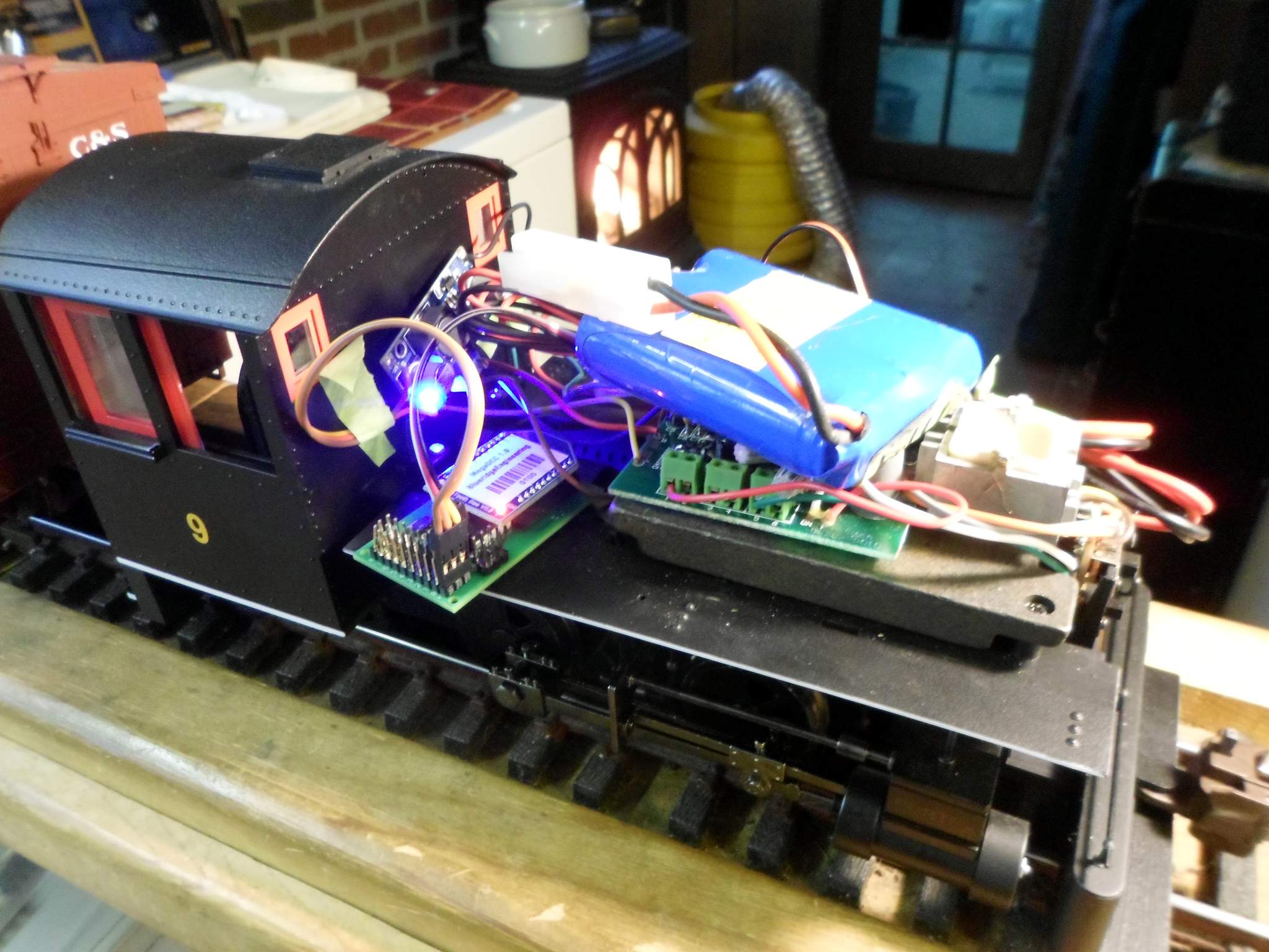
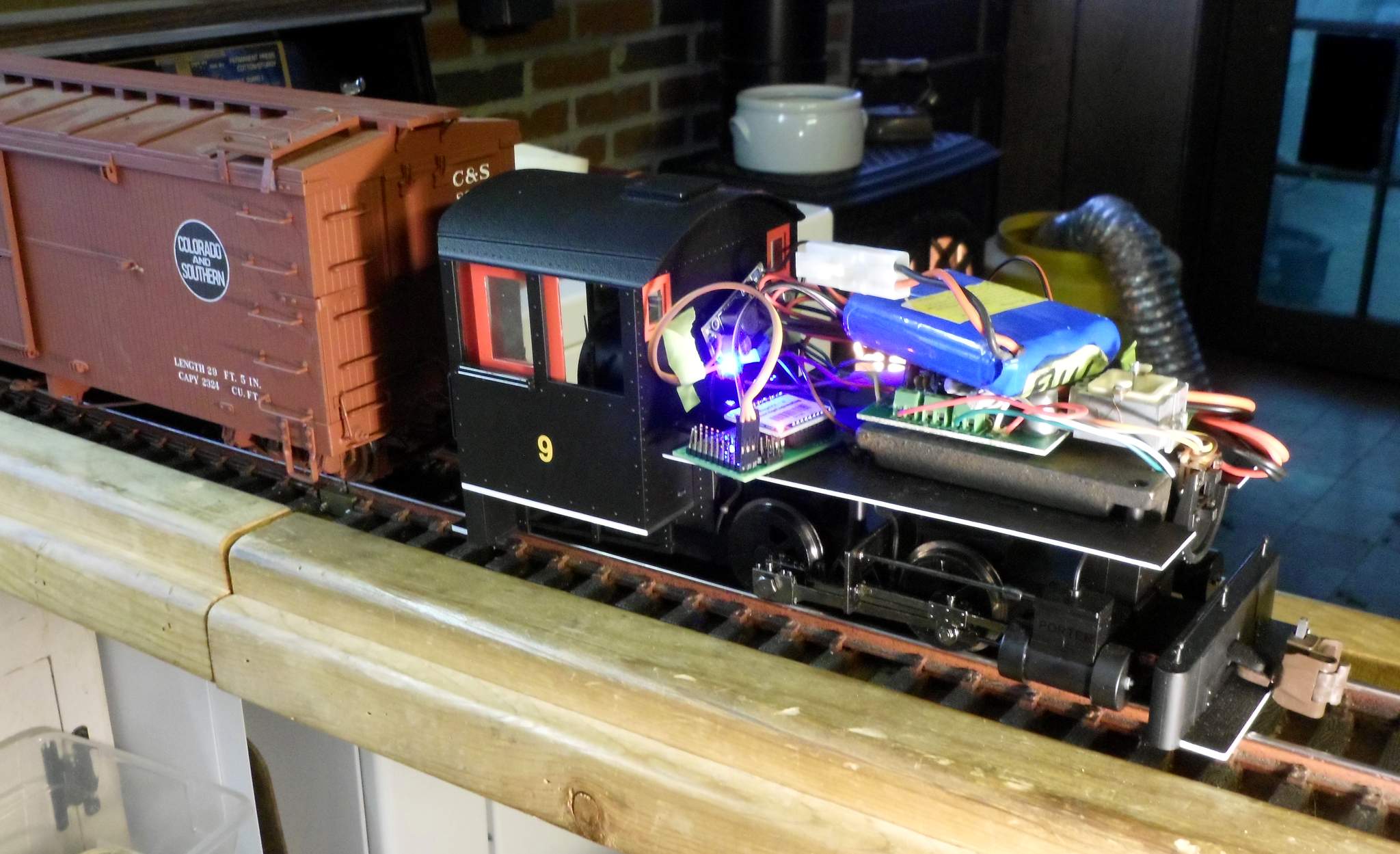
Today I took it to the next level and temporarily attached it all to a Bachmann Saddle Tank Porter so I could get a feel for how this will work in an actual locomotive and try some switching operations. I took a bunch of pictures which I will share with you now. This photo of the fireman’s side shows my very temporary set up. 11.8V LiIon battery on top, the blue ESC is on the running board and a voltage converter is taped to the firewall. All that excess wire is left over from bench testing. I was just too lazy to reconfigure everything…

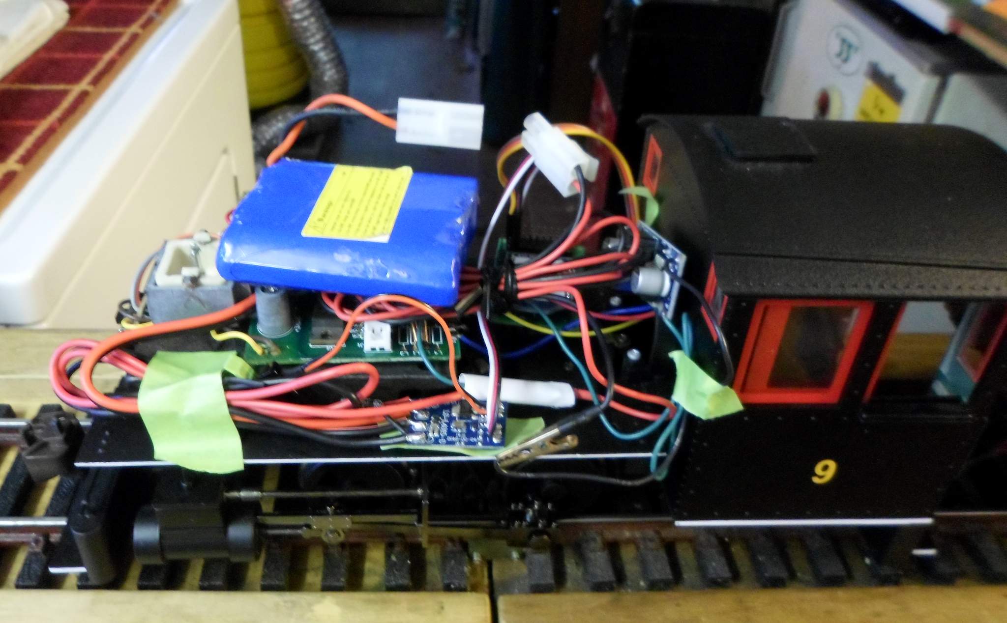
I left the Bachmann circuit board in place (for now) but only the motor circuits are being used…

This is the Powerday ESC. I cut off the heat shrink and added my own leads for Battery and Motor since I didn’t have any of the mating JST connectors the board came with. This model is Center Off with no brake…

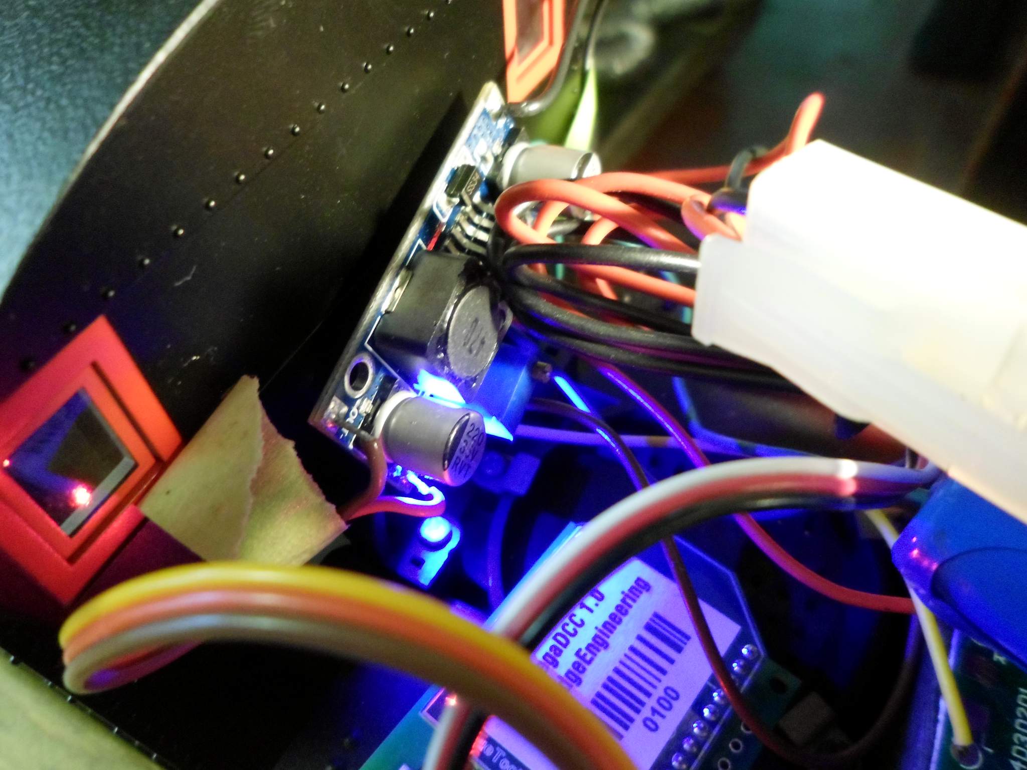
This is a close-up of the eBoot DC-DC voltage converter. It also came from Amazon in a 6 pack for $12. I am using it to derive 5VDC from the battery. It works very well and holds the output voltage to within .002 volts so long as battery voltage exceeds 6.5V. I use the output to drive Martin’s board and will also use it as a voltage source for LED lighting…

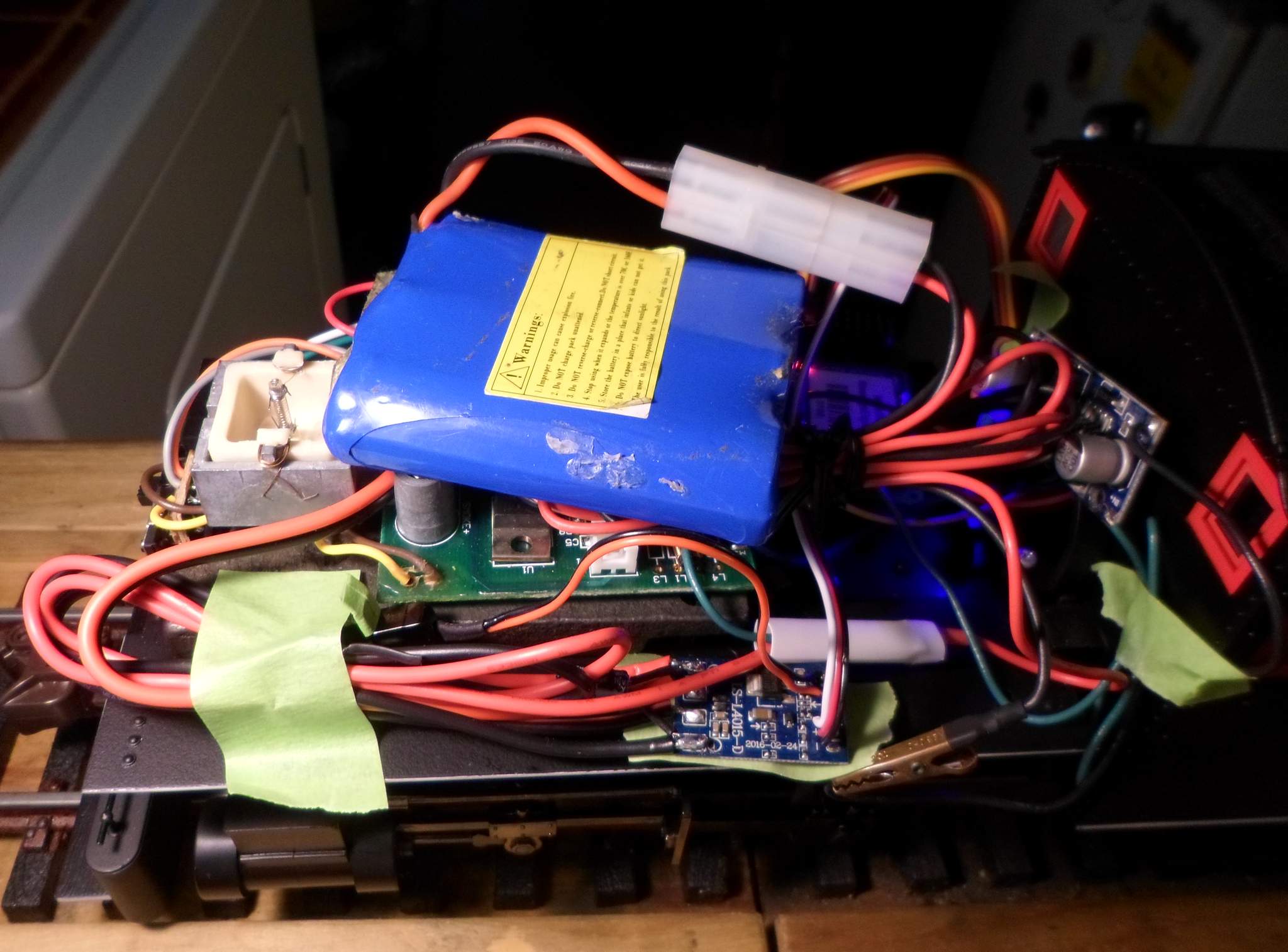
Over on the Engineer’s side you can see the other side of the DC converter and Martin’s board on the running board…

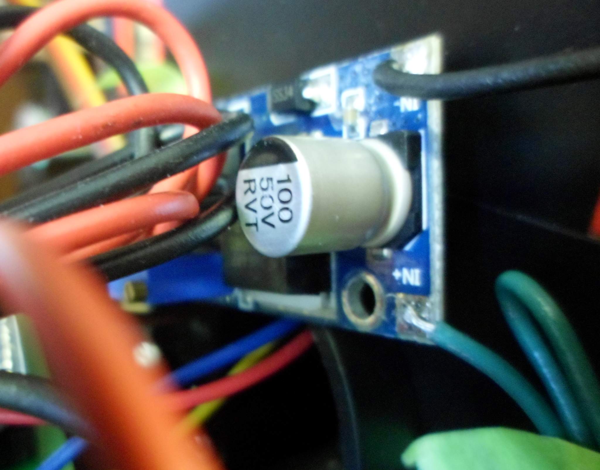
Close up of the other side of the SC Converter…

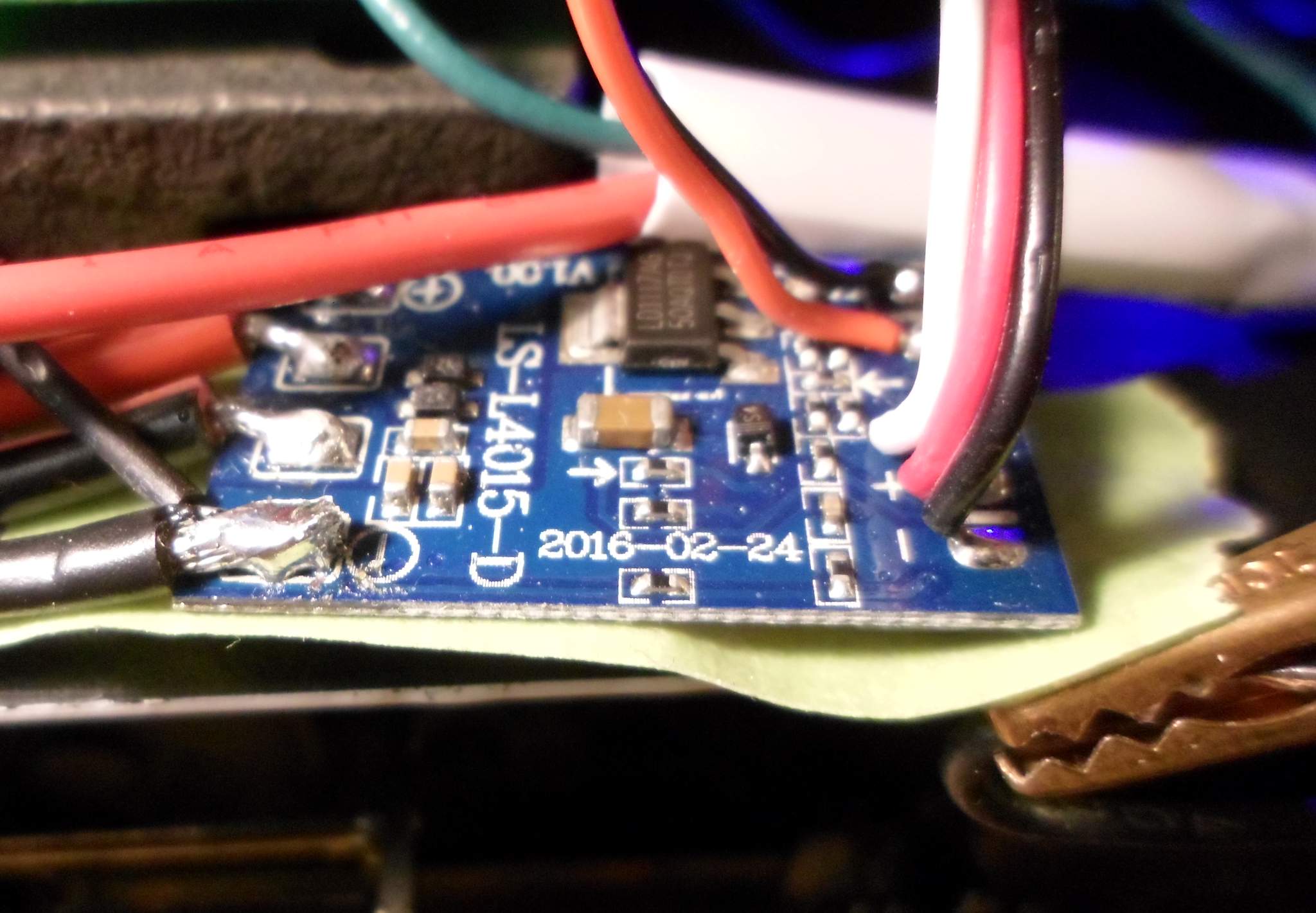
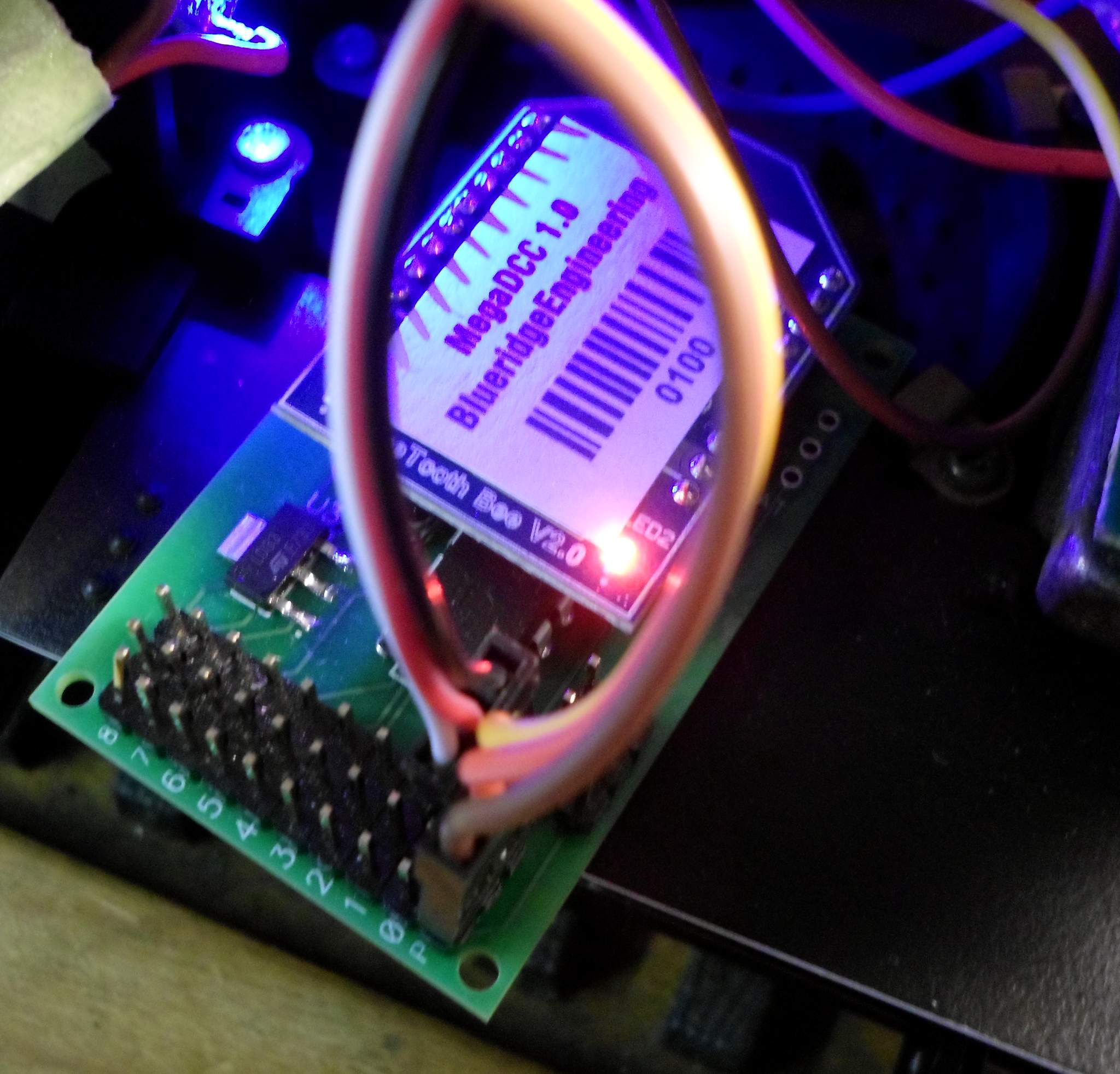
And a close up of Martin’s board. The yellow wire of the cable connected to P is not connected to anything. The Red and Brown wires power Martin’s board with the 5V output of the DC Converter. Only the data line feeding the ESC is connected to servo output 0. I found that if I used the BEC output of the ESC to power Martin’s board, the ESC would power up in full throttle regardless of the position of the on/off switch on the ESC. Wired in this way the on/off switch works to keep the ESC off line until the Bluetooth system is powered up and linked to the app. When the app is linked, powering on the ESC last keeps the motor at zero throttle as the ESC comes op…

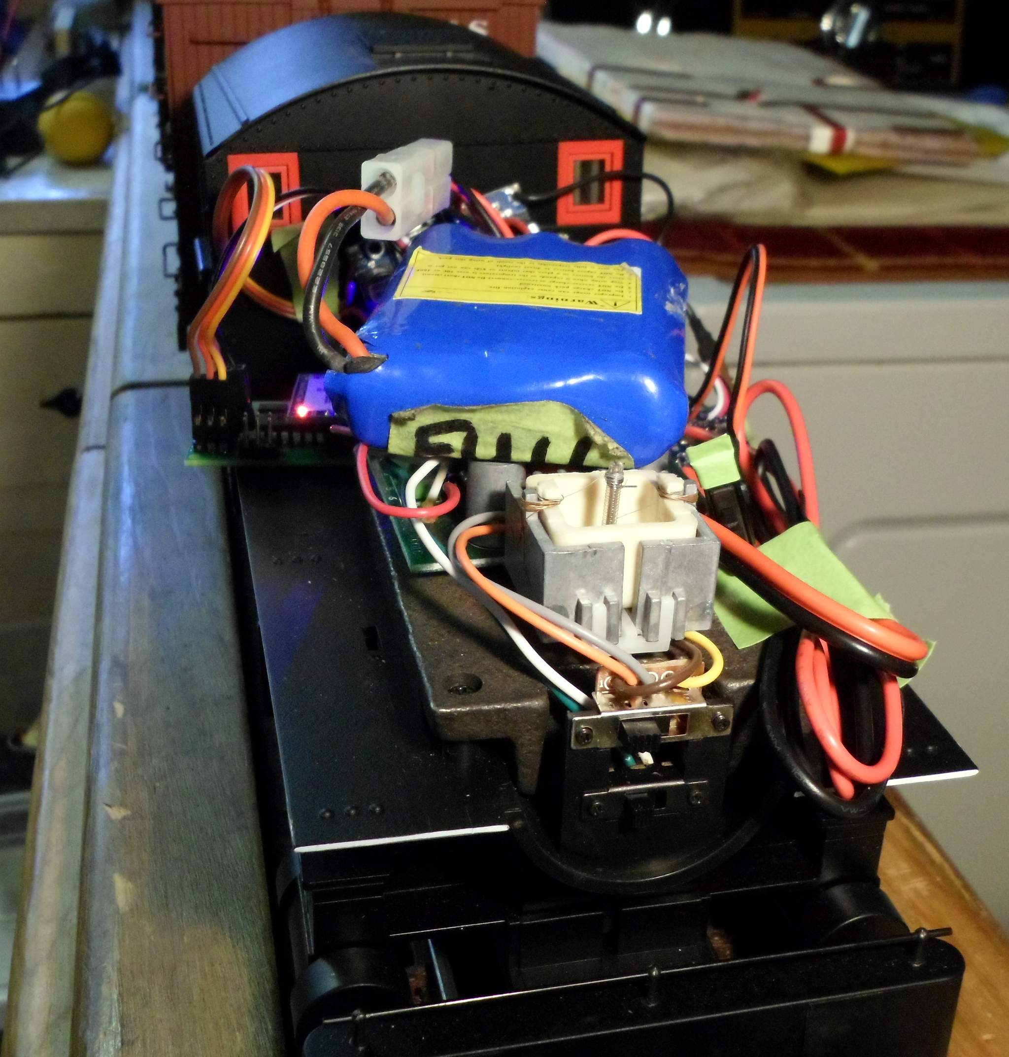
Front view of the test set up. The Orange and Grey wires from the switch are tied to the Motor Output of the ESC. This came directly from Bachmann’s documentation as the motor connections for a DCC decoder…

I did some running and switching with this single boxcar. I was quite happy with the throttle response although the top-end speed with 11.8V was a little slow. I tried later with a 14.8V pack with much more pleasing results…

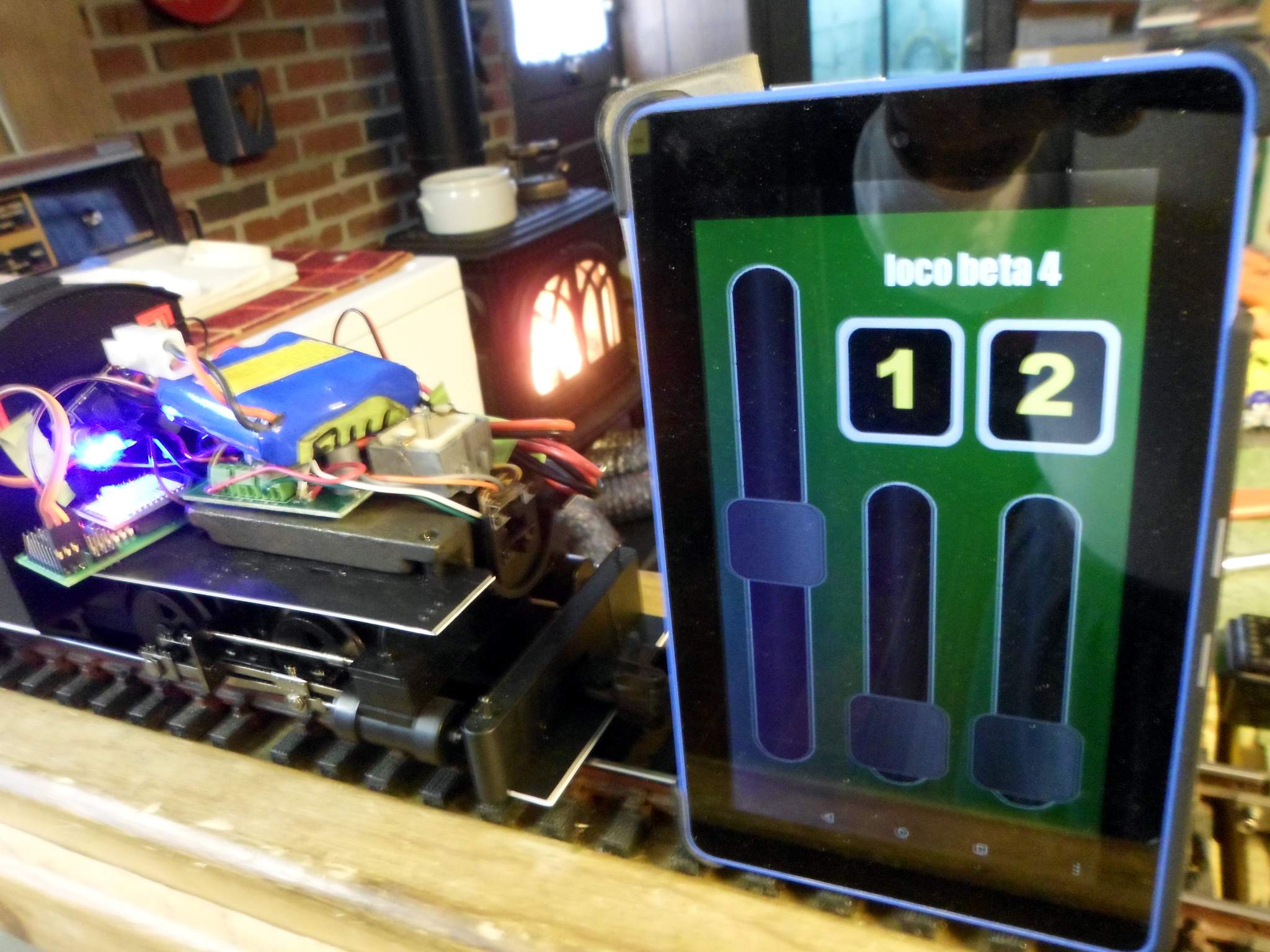
I am using an Amazon Fire 7 tablet ($35 Christmas 2015, $39 Christmas 2017, Regular $49) to run the Android Bluetooth app. The screen shown is Martin’s Generic R/C app - Three servos and two digital logic (5V on/off) buttons. The board’s DCC Throttle output tracks the throttle servo output for hybrid setups using a DCC decoder for sound and lights…

I think I am just about ready to commit to installing this system in this Porter for use as a captive switcher at one of my indoor yards. There is one minor issue that I need to sort out. I think it is the fault of cheap the ESC and I’m hoping I can smooth it’s output: When at low throttle positions (forward or back) the motor in the Porter squeals quite a bit as the ESC sends widely spaced pulses. As the throttle is raised the frequency of the squeal increases until it goes away at about half throttle. Any electronics gurus that care to give some advice on how to eliminate that, please speak up (https://www.largescalecentral.com/externals/tinymce/plugins/emoticons/img/smiley-wink.gif)The ESC has a 100Mfd electrolytic filter cap on the battery input, but nothing on the output. ESC gets all it’s power direct from the battery.

The squeal is from the motor PWM frequency.

The only way to get rid of it is to use an ART 57091 in between the ESC and the motor.

Be warned, doing so you will likely lose a degree of low speed smoothness from the ESC.

Do not put a capacitor across the ESC output. The cap will make the ESC overheat.

See if you can find an ESC with a PWM frequency above 10 - 12 KHz

Thanks Tony. This was a quick price based purchase just for testing. The ESC I bought is center off with reverse. I have decided I would rather have a full throw, no reverse ESC and use a relay for direction control. This will allow me to use the 14V battery for better top end speed and full travel of the servo controller for better control. I will be using this loco for R1 yard switching duties so I need good low speed control. I will take your advice and be mindful of the PWM fequency as I shop.

For the “Low OFF” control you envisage, I would be devising some sort of lock out control to prevent the relay accidentally allowing change of direction when running.

Otherwise severe damage could result to the loco drive train.

Tony Walsham said:

For the “Low OFF” control you envisage, I would be devising some sort of lock out control to prevent the relay accidentally allowing change of direction when running.

Otherwise severe damage could result to the loco drive train.

Good point Tony, and Martin has thought of this…

“With the first option, the 8A relay board is tied to one of the widget digital outputs to control direction. The drawback to the relay is that it can, in theory, be switched while the locomotive is under power- this is not a good thing. So the app side locks out the relay output unless the throttle is at zero.”

Hi Martin

I am new to this forum, so please excuse the forwardness of my post.

I have modelled HO using DCC for years but am trying G scale in the garden for the first time.

I have been looking for a control method using existing smartphone without using an expensive system like Airwire or Digitrax with a PC and JMRI etc.

Your solution is ideal.

Problem is how do I order one?

I see your website says out of stock.

Any updates on this please.

Cheers

Gareth

Hi Gareth. I appreciate the interest. I’ll just go ahead and post an update here as I have been meaning to get to that.

Right now I am still in beta test mode. The control board itself is in very good shape, I have fixed some things pointed out by the testers and I have found a few on my own. So that part is solid. I’m up to firmware release 1.04 and have not changed it in some time.

However, I have a slight problem on the Android side. I have several apps I have built using a particular software package and they work well with one big exception- they crash on Android version 7 or 8. Android releases 4, 5 and 6 are all fine but if your phone is Android 7 or 8, nope. Doesn’t even run at all. Turns out Google changed some low level things when they went to version 7. (surprise!) I won’t go into all that but suffice to say that the folks that do the package I was using have no intentions of fixing it so I am kinda stuck.

So I’ve been forced to re-write the app in Android Studio. I am not a big fan of Java, or I wasn’t, but Android Studio turns out to be way way cool, I used Eclipse back in the day and it sucked rocks (IMHO), so I was pleasantly surprised. Anyhow, I can re-use the art and some of the data structures so it’s not a total rewrite but it’s going to take some time. I am about 1/3 of the way through, I have the basics working, I can connect to the board via BT and do the basic DCC stuff but since I am in the guts of it again I’m planning on enhancing the app while I do this. From my own personal experience I don’t like using multiple apps for different decoders so I’m making the new one ‘smart’. You can name the Bluetooth board to your locomotive name and you see that name when you pair your phone with it. So what I’m going to do is allow you to configure the app, based on that name, to use a particular configuration for whatever decoder is in there. Choose the locomotive on the phone and the app ‘automatically’ knows what buttons go with what DCC functions, etc. It’s actually not a big change, or not too much, but I have to get all that coded up and tested and I can only work on it part time. (I had many many months in the older apps) I will probably release a ‘basic’ version in a few weeks though just to get it out so folks with newer phones can at least run it.

Well, long story there I guess but if your phone is version 4, 5 or 6 (it’s on about 50-60% of the cheaper phones) and you are interested in a ‘pre-production’ version, you can email me at:

[email protected] and we can chat further.

Thanks.