Large Scale Central

Beating the Boredom HO Tyco Hooterville Cannonball

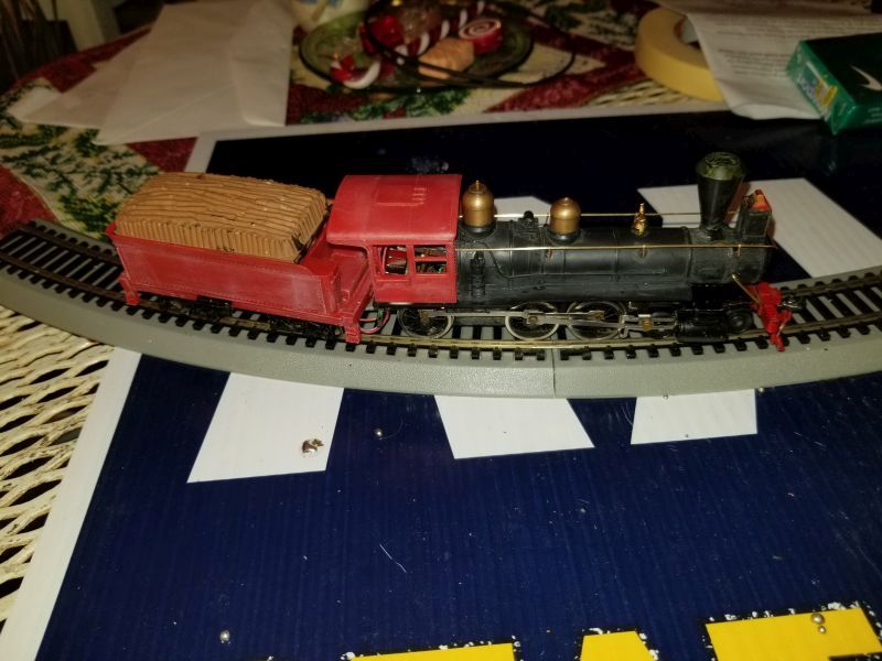
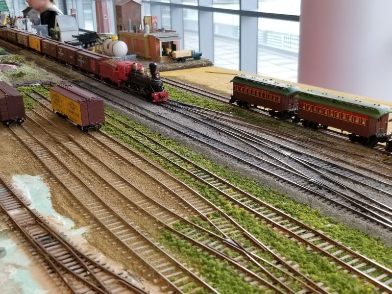
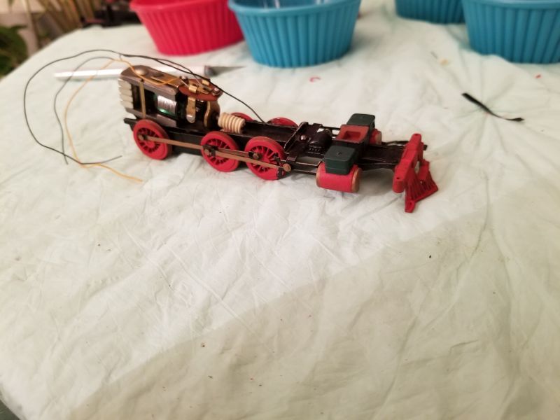
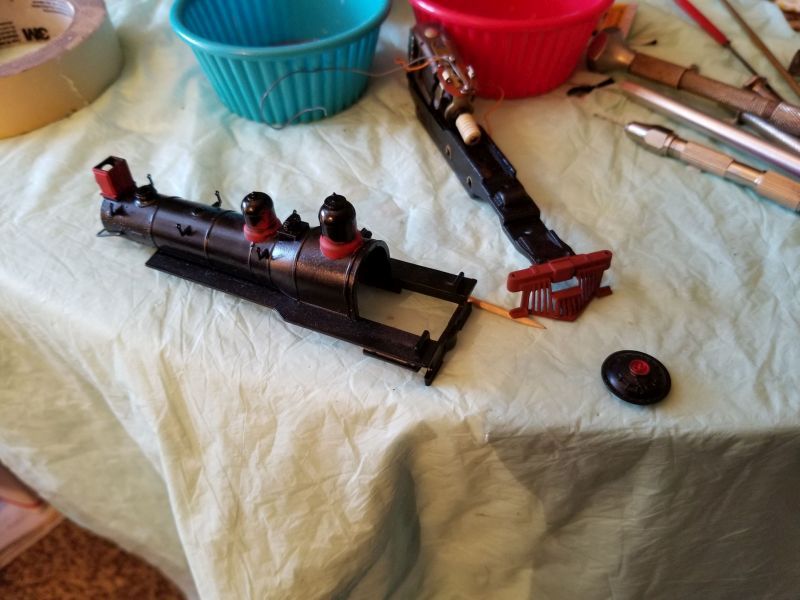
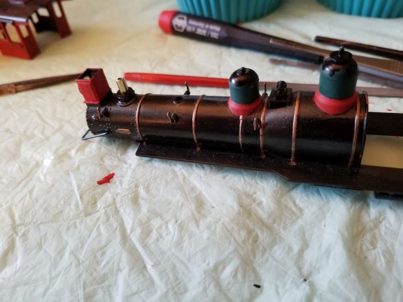
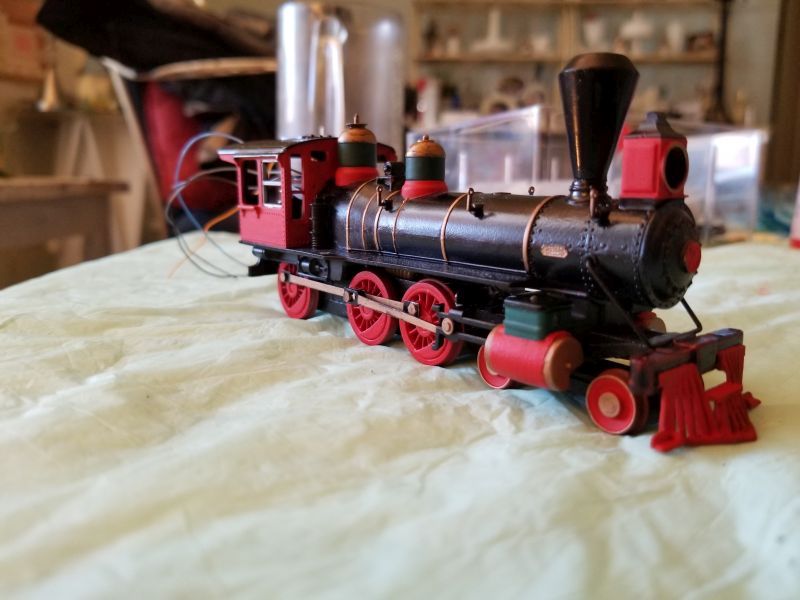
Ok, Since Devon asked for it, I will start my thread on my kit-bashing of a Tyco 10 wheeler into the Hooterville Cannonball.

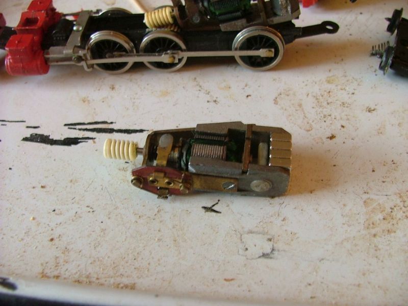
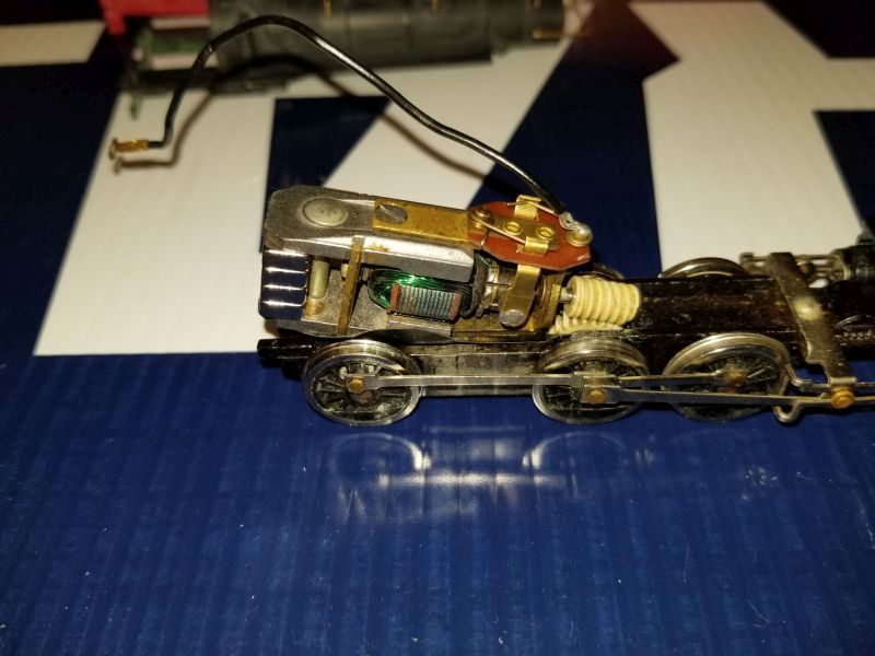
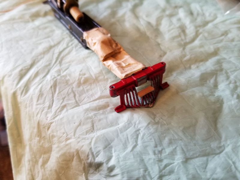
As with all my Tyco rebuilds so far, I start with replacing the motor magnet with super magnets from Micro Mark. These magnets are much stronger then the original magnet, and cut the current draw of the motor nearly in half. I also adjust the bearing plates to remove most of the lash from the motor, and lube the motor bearings with a drop of oil. Then I power up the motor and run it both directions for a while till it settles down and will run at a nice slow speed. Most times these motors haven’t turned for a few decades, so they need a little time to run the stiffness out of them.

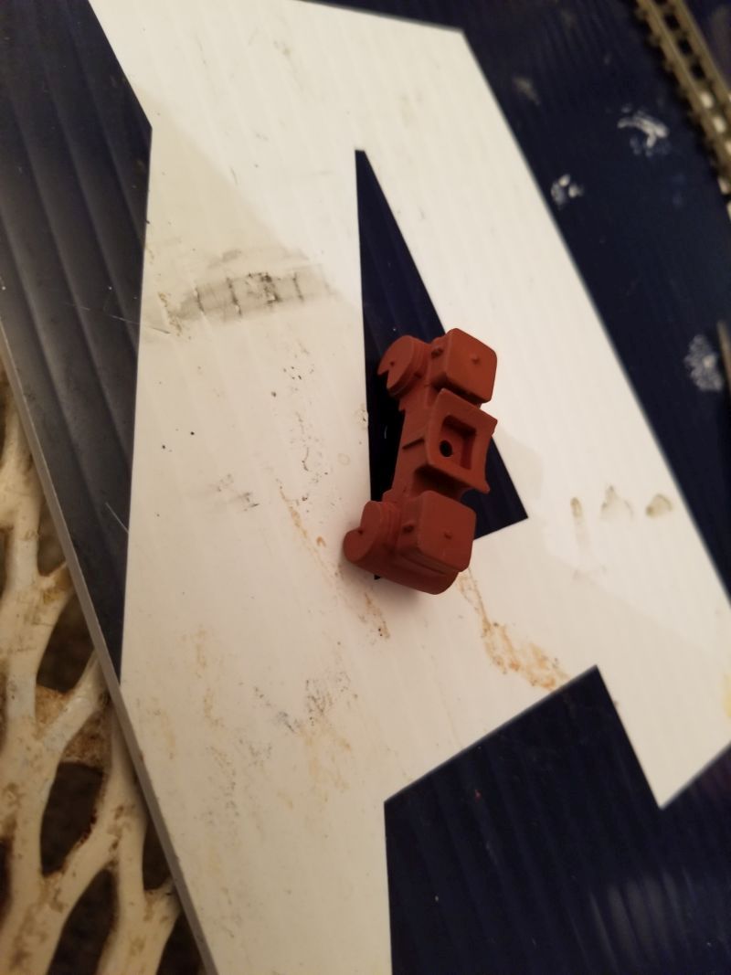
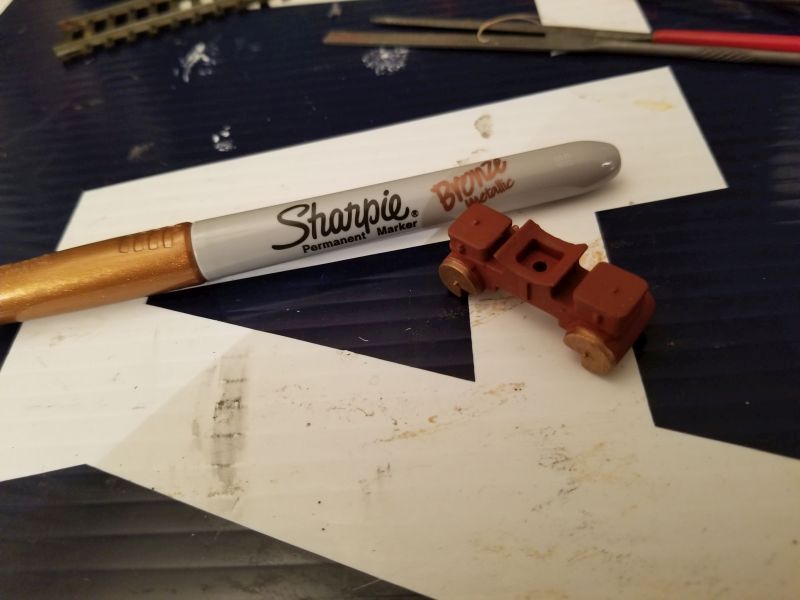
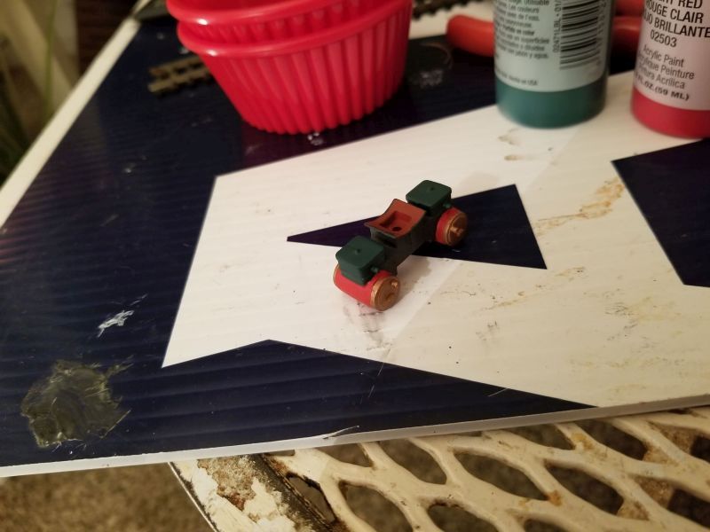
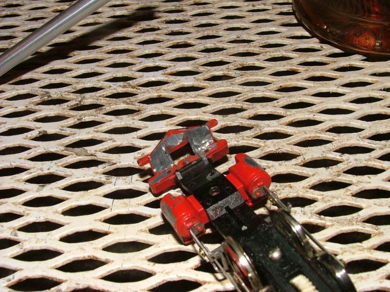
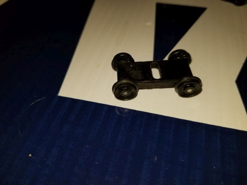
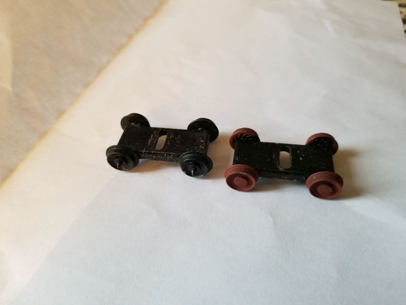
Then I replace the rear driver with one that does not have the traction tyre.

The traction tyre stands proud of the tread, almost as far as the flange. This can cause derailments. To get the needed drivers, I purchased 2 “for parts” (trashed) Tyco Mikados. The Mikado uses the same drivers as the 10 wheelers, but none of the Mikado’s drivers have a traction tyre. Only the first and last driver of the Mikado are flanged, but for the price of a junked locomotive, I can fix 2 10 wheelers.

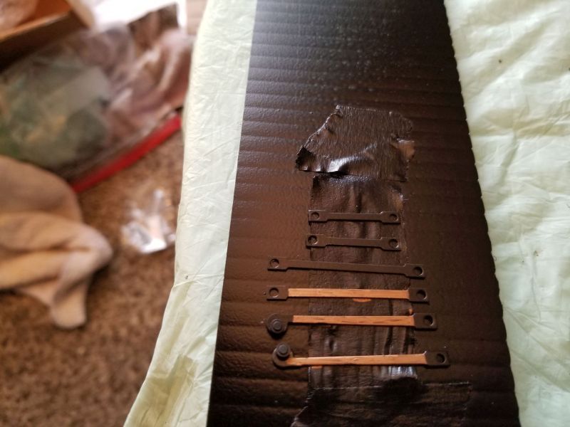
To isolate the motor from the frame, I put a layer of electrical tape on the bottom of the motor, and reattach the motor with a KaDee, Nylon, 2-56 screw, trimmed a bit for length.

Of course while I have the bottom plate off to replace a driver, I clean the dried lubricant off the axles and axle bearings, and re-lube with some Lubriplate that found its way to my house one day. I also put a drop of oil on the crank pins and cross-head. Then I power the thing up and run it both directions to make sure there is no binding or odd noises. Once the drive passes inspection, then I can move on with the rebuild or bash.

Next I worked on the steam chest. The cylinders were cast with a slight bulge in the center. I guess that is so they would easily de-mold when they were cast. After filing the sides of the cylinders flat, I gave them a good coat of oxide red primer.

Then I painted the ends brass. Ok, I didn’t paint them, I drew on them with a Bronze coloured Sharpie.

Then I painted the steam chest with craft paint.

Once I was satisfied with the steam chest, I gave it a good coat of Krylon clear flat .

The solid Tyco pilots, with the added “features” to them always bothered me. So I set out to modify the pilot. First I ground the back of the pilot thinner.

Then I ground the extra “features” off the front of the pilot, and day-lighted the pilot. In the process, the center part broke out, so I reattached it and used a bit of strip-wood along the top to attach the broken out center part.

Its not perfect by any means, but I am not going for an exact scale model, just a good enough representation.

I like the bronze sharpie idea.

This project works for sure. I could care less if its G HO Z or ride on. Jus as long as w all have something to share. Thanks David

You are welcome Devon.

I soaked the plastic parts in Pine Sol for a couple of days, taking them out from time to time to scrub the paint off the parts.

The locomotive shell was black, then factory painted painted black, then the boiler jacket area was painted green. The cab was red, factory painted red, and then stamped with the artwork, and the tender shell was done the same way. The artwork came off after just an hour of soaking, the first coat of paint came off after a day, but it took 2 days to get it all off.

Last year I had stripped and reassembled another 10 wheeler. It was a “prof of concept” prototype. Actually, it was to become the Hooterville Cannonball, but I like the “shake the box” kit look of it, so it runs naked at the shows.

This locomotive proved that even without a traction tyre, the locomotive can not only still run, but can pull a decent train.

Also, it proved that my home made, shorter draw-bar idea works just fine. As does my routing of the wires through the tender floor, and below the level of the draw-bar.

Success is a good thing; and a solidly engineered model sure makes success easier to achieve.

On the Tyco pony trucks, they just used the same axles that they used in the trucks. So the axles extend beyond the wheels, and come to a point. That is another detail that just looks wrong to me. So I filed the axles flush with the wheels.

Then I gave the wheels a coat of primer. On the left is a pony truck in it’s original condition.

Then I painted the face of the wheels with my red craft paint, and drew on the wheels with my bronze Sharpie.

This is odd, I can’t find the picture.

Yes that looks way way better

After stripping the paint from the boiler, I carved off the feed water pipes. Molded on piping looks, well, molded on. I was going to carve off the air pump and replace that too, but I decided that was a “detail too far”. Yes, I “borrowed” that phrase from someone here. Again, I am trying to achieve a good representation of the Cannonball, not a scale model. Then the boiler that got a coat of semi gloss, Krylon black.

A few spokes in the drivers were miscast, I guess its either a defect in the mold, or there were air bubbles trapped in the mold. So I built up those areas with some super glue and baking soda. I was going to use JB Quick, but the one tube I had was partly dried and the stuff wouldn’t mix up right. Once the super glue/baking soda patches set up hard, I carved them to shape, and then primed the drivers with Kylon ruddy brown primer. After the primer dried, I gave the drivers a few coats of red craft paint. After letting the craft paint dry for a couple of days, I coated the drivers with Krylon clear flat.

The drive rods got a good coat of Krylon semi gloss black, and then I drew on them with my Bronze Sharpie.

I painted the pilot with Krylon ruddy brown primer. Then I painted on a few coats of my red craft paint, and once that dried, I gave it a coat of Krylon flat clear. Once the plot was done, then I assembled the chassis. I cleaned the black gunk off the axle bearings, and the gunk and paint over-spray off of the axles. Then I lubricated the axles with some Lubriplate. I coloured the crank pin bolts with my bronze Sharpie and assembled the chassis.

You can see the wires from the motor, and frame, that will go to the DCC decoder.

Then I realized that I had goofed. The Pilot beam is supposed to be black, as well as the top of the steam chest. Well, I will fix that when I use my chalkboard craft paint to paint the cab and smoke-box.

After putting a drop of oil on the crank pins and cross-heads, I clipped an HO power pack to the motor, and ran the drive forward and backward. It runs smooth, and will even run at a very slow speed. Not that Tycos are known for their slow speed running characteristics. (https://largescalecentral.com/externals/tinymce/plugins/emoticons/img/smiley-wink.gif)

Ok, I have been remiss in posting to this thread. So since the last posting, I had pained the boiler with Krylon semi gloss black. Once that dried, I painted the light, and bases of the domes, with a few coats of my red craft paint.

Once that dried, Then came a few coats of green craft paint on the domes.

And I started colouring in with my Bronze Sharpie. You can also see the brass tube I mounted into the the boiler, so I can reattach the stack.

After the paint, and colouring the bands, builder’s plate, and dome tops with the Sharpie, I did a trial assembly to see how things are looking.

On the cab, I used a silver Sharpie to colour the aluminum window frame in the cab.

I need to do another coat of black paint on the pilot beam. Once I did that, I started Devoning about the artwork on the cab and tender.

The prototype artwork is partly done with applied printed artwork. I didn’t want to do mine that way, since I thought it would look like I cheeped out. But the more I think about it, the more I am warming up to the idea, Its how the movie studio did it on the real locomotive, and it would be a lot easier for me to do it that way on the model.

David,

This is an inspiring restoration. Thanks for taking the time to detail each step. I am plotting my “Rehabilitation of the Missile Sponges” some time in the indeterminant future, and this is a really cool study of the possible.

Aloha,

Eric

While I am not sure what a Missile Sponge is, I have been into restoration of models for decades. It allows me to have more then I can afford new, and it also allows me to have what I want, that may not be commercially available.

David,

“Missile sponge” is a Navy term for the ships that were supposed to take the hits - absorbing missiles as a sponge absorbs water - to allow the carrier to carry on her mission. In my case, it is the lower cost, battery powered items that let the kids have trains of their own that worked in the garden, absorbing the blows of well intended toddler hands, and thus minimizing the risk of damage to more expensive items. We are aging out of that period of our lives, which allows me to consider repairing superficial damage for those on the model end of the spectrum or examine the art of the possible at the toy end of the spectrum. Like I said, really, really nascent ideas right now, with no intention of putting plans to action just yet, and threads like this help scope the planning efforts.

I also really enjoyed the challenge of figuring out how to get my old LGB fleet back into action after its long hibernation. Some worked out of the box. Some needed some investigation and repair. That m2071D defies every effort to get it rolling. Success or failure, by and large, these repair efforts had a positive bleed over effect into other areas in the 1:1 scale word. It is more tinkering, I suppose, than restoration, but it is satisfying.

Thanks,

Eric

Missile sponge, designed to take the hits. I see. In a related note, I put “sacrificial rails” on my modules. Sometimes during tear down after a show, someone in a rush to tear down, doesn’t remove the connecting rails between modules before disconnecting the clamps that hold the modules together. Then they end up ripping the rails off a module. So the last 2 inches of my rails are not connected to the rails on my module with rail joiners. They are just glued in place. A few shows ago, a well intentioned newbie ripped off the sacrificial rails from one end of my modules. Replacing 2 inches of rail was a whole lot easier then replacing the turnouts that abut the sacrificial rails. So my design did just what it was intended to do. The sacrificial rails “took the hit”, protecting the rest of the track-work and turnouts.