Large Scale Central

Reverse Engineering the Bachmann Optical Chuff Sensor

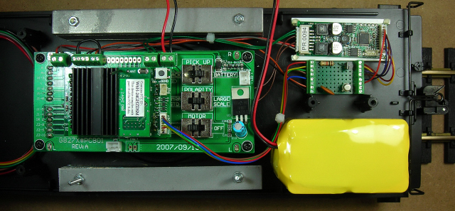
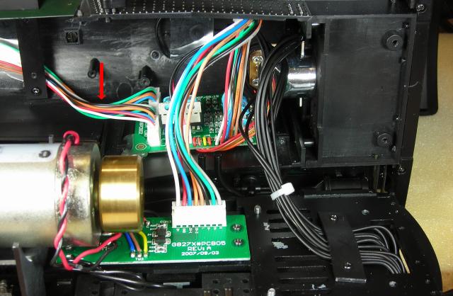
I am in the process of a R/C battery conversion on a Bachmann Climax. Although I gutted the Bachmann electronics, I kept the optical chuff sensor. For those of you who may not understand how optical chuff sensors operate, here is how I adapted it for use with a Phoenix P8 sound card.

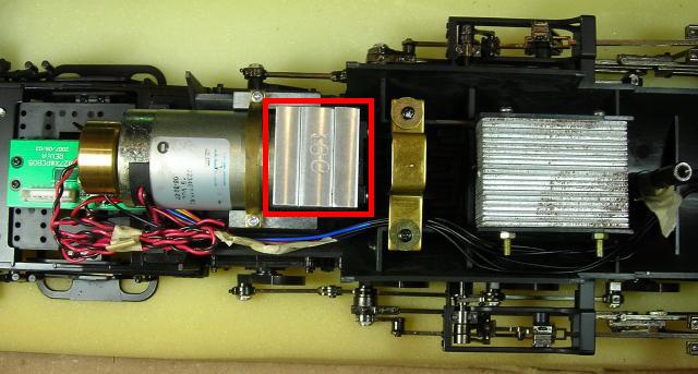
There are two identical optical chuff sensors in the Climax; one for each cylinder. Each sensor provides two chuff pulses per rotation of the counterweight. I only needed to use one of the sensors since I will be using the Phoenix P8 to double the number of chuffs per pulse. Here is how I wired the sensor:

chuff logic

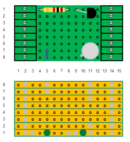
The block shaded in gray represents the Bachmann sensor. There are four wires to the sensor: brown, red, orange, and yellow. The brown and red wires connect to the anode and cathode of an IR LED. The orange and yellow wires connect to the collector and emitter of a photo transistor.

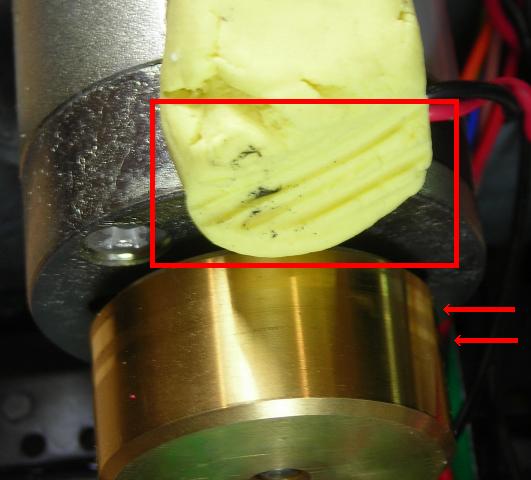
The IR LED is on continuously when power is applied. The light is reflected back into the photo transistor twice during each revolution of the counterweight. When the IR light hits the photo transistor, it conducts and takes the chuff output to ground. When the light does not hit the photo transistor, it does not conduct and the chuff output goes to +5 volts.

The +5 volts is derived from the main battery. I used a ¼ Watt, 5%, 270 ohm resistor to set the current through the LED and a ¼ Watt, 5%, 1000 ohm resistor to provide pull-up for the collector of the photo transistor. The chuff output connects to TRIGGER1 on the Phoenix P8.

I used a high efficiency D24V5F5 500 mA switching step down (buck) voltage regulator from Pololu to derive the +5 volts from the main battery.

voltage regulator

The Phoenix seems to trigger equally well when set to either positive or negative chuff trigger.

Bob

I used the circuit that both Tony Walsham and Phoenix Sound have on their websites. The components used are a 2N2222 or equivalent transistor, and a 0.1uf capacitor. The transistor and capacitor can all be purchased from Mouser Electronics under the part numbers 511-2N2222A and 81-RDEF51H104Z0K103B respectively.

P8 Interface Board

I added them to a small circuit board that also contains volume control components for the P8.

K27 P8 Installation

Both work well.

Detailed instructions on how to assemble the interface board are on the OVGRS web site in the article on adding a P8 to a battery powered and radio controlled K27.

cool

Paul,

I think you missed the statement that “I gutted the Bachmann electronics except for the chuff sensor.” Tony’s and Phoenix’s solution only works if you leave the Bachmann electronics that interfaces to the sensor intact.

I always strip out all factory-installed wiring and circuit boards and start from scratch. I have multiple locos including a K-27, C-19, Shay, Connie, Ten-Wheeler, Galloping Goose, and the Climax and none of them have any of the original electronics or wiring.

I realize not everyone necessarily guts their locos before converting, but thought this approach might be of interest to those who do.

Bob

Bob, can you explain why you gut the locomotive’s electronics?

David,

I sometimes ask myself the same question … why? Especially after I have totally disassembled a $2500 Accucraft loco and have a jillion pieces scattered across the work bench. See my post at c-19-battery-conversion to see what I mean.

I guess it boils down to three things: performance, appearance, and reliability. I used to model in the smaller indoor scales – especially Sn3 (1:64 scale, 3 foot narrow gauge.) We had a term for the best running, best looking, most reliable locos. We called them “FOREGROUND MODELS.”

Nothing that is mass produced ever comes that way from a factory. It always needs a tweak here or there to optimize the mechanical performance. And disassembly allows one to do unique customizations and detailing. Besides … painting and weathering is always easier when you have a model apart.

But the most important factor, IMHO, is eliminating the bugs in the electrical design and assembly – cold solder joints, cheap switches, questionable parts, etc. I really enjoy building a model where I have 100% control over the wiring, the parts selection, and the documentation.

You may think I’m crazy (I’m not … my mother had me tested) but I actually get a kick out of doing it my way. It takes a bit longer but I really like the results.

Bob

Bob, ok, I understand. I thought maybe it was just because its easier to start with a blank slate, then to try and interface with what the locomotive came with. As for cheap switches and questionable parts (quality), I completely understand.

Besides the reasons that Bob gave, all of which I agree with, there is also this issue of wasted power in the factory electronics. When running on track power things like voltage regulators and current limiting circuits are important. Not so much when running battery power with a fixed voltage source. These additional items don’t draw a ton of current, but every little bit of wasted current contributes to reduced run time.

I used to like smoke and even upgraded one of my Annies to the SD-45 smoke unit to get more volume. When I went battery I quickly convince myself that if I really need to see smoke I should run live steam (http://www.largescalecentral.com/externals/tinymce/plugins/emoticons/img/smiley-wink.gif)

Under battery power I can see that. But I know some track power guys do the same, strip out all of the electronics and start over. I was just wondering what the idea is for that. Now I know.

The K-27 was the only engine I didn’t gut, simply because what I got from Don Sweet was a drop in, plug-and-play board. I never did get those optical chuff sensors to work, so I added some magnets and a reed switch to on of the tender axles. Later on Paul Norton explained to me what he did to get them working.

On newer locos, many have screw terminals and you can completely isolate the track pickups, motor, lights, etc.

In those cases I normally leave the electronics in place, they are just not used.

Now, I’m running track power, so I normally have lots of space to place a (single) decoder and speaker.

If I was running battery, and also you normally need TWO circuit boards inside, one for the motor and r/c and the other for sound, then space is almost always at a premium so I would most likely remove the original electronics.

Greg

The K-27 tender is big enough to hold a battery, receiver, P8 sound board, sound interface board, and speaker. I left all the electronics in the tender in tact.

A styrene platform was added under the coal load for the battery switch, charging connector and P8 programming outlet.

K27 switch panel

Four of the weight bars were moved to the opposite stack to compensate for the weight of the CR1755, 14.8 volt, 4000 mah, Lithium-Prismatic battery.

K27 weight stacks

Screw terminal blocks were added to the PnP board solder pads to make the wiring easier.

I had more trouble getting the wiring and fan out of the way of the added reduction gearbox so the locomotive did not teeter-tooter on the 3rd set of drivers. After that K ran well and sounded great!

And why do we still have to “upgrade” new locomotives?

Customize…(http://www.largescalecentral.com/externals/tinymce/plugins/emoticons/img/smiley-wink.gif)

I had more trouble getting the wiring and fan out of the way of the added reduction gearbox so the locomotive did not teeter-tooter on the 3rd set of drivers. After that K ran well and sounded great!

I had that same problem. Couldn’t figure out why the boiler wouldn’t fit back on. Removed the smoke unit and moved the circuit board for the front lights up a bit, boiler fit just fine.

Converting a K is a piece of cake with all the room to spare, especially in the spacious tender. I can see why some folks might leave the factory-installed electronics intact. However, gutting factory-installed electronics is almost a necessity when working on smaller locos. For example, the Climax I am currently converting (which is how this thread got started), has precious little space for two decoders and a battery. When you stop to think that I am also adding dual speakers, the task becomes even more daunting. I ended up putting the G3 decoder in the boiler, the second speaker in the diamond stack, and the 3000mAh battery in the fuel bunker above the rear speaker. The Phoenix P8 fits into the fuel bunker as well. I even had to chop a bit off of the weight to have adequate room in the tiny boiler. These photos will help to explain why removing extraneous factory-installed electronics is so important.

Original weight removed from boiler:

Weight modified by removing 3/4" from front:

Front and rear portions of boiler with modified weight reinstalled in rear portion:

Test fit of CVP Products G3 motion decoder in front portion of boiler, viewed from rear:

Test fit of CVP Products G3 motion decoder in front portion of boiler, viewed from front:

Bottom view of G3 decoder with added breadboard on bottom (attached with double stick tape) to hold voltage regulator, chuff sensor interface, and series resistors for headlight, cab light, ash pan flicker, and firebox flicker. This photo shows the new pigtail and external antenna which will also fit in the boiler. Wires to the right go to the headlight, front speaker, front motor, and P8 programming jack (will be hidden behind smoke box door) wires to the left go to the fuel bunker, rear motor, cab, firebox, ash pan, and chuff sensor:

Same as previous photo, only top view. You can see where the pigtail snaps onto the G3 connector where the original antenna was connected:

Bob

While testing a Bachmann K27 after installing R and K Railroad Products reduction gearbox, the third drive axle appeared locked in place. This caused the locomotive to teeter-totter on the third set of drive wheels. As this would probably reduce the tractive effort of the locomotive and encourage derailments, the locomotive was opened to investigate the cause of the problem.

K27 Reduction Gearbox

The investigation revealed the installation of the R and K reduction gearbox had stopped the motor and gearbox from be able to pivot. The reduction gearbox moved the K7 motor rearward about 1 1/4 inches. This unfortunately caused the K27 fan to prevent the gearbox and motor from pivoting normally, and interfered with the suspension of the third drive axle to which the motor and Bachmann gearbox are attached. The impression in the Play-Doh shows the fan pressing on the new gearbox and limiting motion of the motor.

K27 Fan

To eliminate the problem, the fan wires were unsoldered from the K27 printed circuit board, and the fan removed. But that only solved one of the problems. In the area behind the motor is a large printed circuit board with several sets of headers and multi-wire connectors. Now that the space for this myriad of heavy wires was cut in half by moving the motor back 1 1/4 inches, the wires were interfering with the movement of the motor and rubbing on the flywheel.

K27 Flywheel

Although some K27 owners trimmed the mounting posts of the circuit board to resolve the problem, it appeared this would not provide enough clearance for the headers, connectors, and wires on the front of circuit board above the flywheel. Noticing that the motor was offset to one side, it was decided to mount the circuit board in the larger space on one side of the boiler.

K27 Wires

The circuit board was fastened to the side of the boiler with hot glue. The wires on the front of the circuit board were pressed against the boiler and taped in place to insure they did not interfere with the flywheel or movement of the motor. All other wires were routed over the flickering firebox as the boiler was re-installed.

After the locomotive was re-assembled, it was placed on a piece of track. All the wheels now sat squarely on the rails, and all four drive axles now moved freely on their suspension components. The teeter-tottering effect of the frozen third axle had been eliminated. This improved the tractive effort of this fine locomotive.

Paul,

With all due respect, please quit hijacking my thread. This is your third reply dealing with K-27 issues that have nothing to do with my original topic. I was simply trying to pass on a helpful tip about interfacing to the Bachmann optical chuff sensor for those who choose to gut their locos of the factory installed electronics in small locos like the Climax.

I do appreciate your expertise in dealing with K-27 issues – I have two of them myself – but this kind of information belongs in a K-27 thread.

Thanks,

Bob

Here is another perspective on installs for those that can use the factory circuit boards. With the Bachmann and Aristo Craft locos that have the socket you basically plug in board. The motors and lights are prewired. Just add a sound system. I have attached a recent install using the RailLinx Plug N Play board and Phoenix P8. All the electronic gear fits snugly in the tender. I placed the 2 hour lithium battery in the cab.

Bob, I sort of helped in the hijacking, and I’m sorry, I see how things went astray, and there’s a lot of good information in this thread, but as you say, much of it is not on topic.

Thank you for your original information, I do DCC and often have to interface to this circuit.

Regards, Greg