Dave Taylor said:
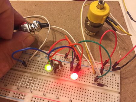
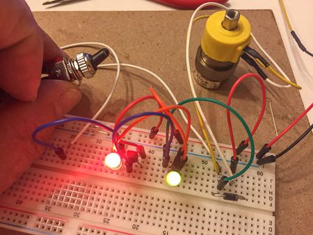
Yup… Just like you said that it would be, But not as bad as I thought. The LEDs are frosted with a wider viewing angle, and actually its the red ones that I wanted to be most noted, as that indicated that that line is blocked. This is a cell phone pic, so no real control of the settings.
OK my newbe ignorance, If I was wanting to “Balance” the intensity I would have to restrict the current to the red side by adding a resistor, thereby making it not so bright, Or, increase the current to the Green side, making it burn brighter, but greatly reducing it’s lifespan. OR both? If I put a resistor in series to the red side to decrease the current and it matches the green side, If my voltage changes, then all bets are off as to the “Balance”, or with the CL2 controlling the input, would the resistor in series on the red leg of the LED just help control the red side, and have no effect on the green side?
I don’t think that you would be able to simply add an additional resistor on the red side because the current limiter would try to compensate for this and allow more current to flow when the red is on. But you can try it in series and/or parallel. Worst that can happen is you fry more parts.
If you end up using two “devices,” they may as well just be the resistors, which as I noted are cheaper and you don’t need to think about polarity (as you found out).
You know how to do the calculations and have the pieces to try various combinations. Just shoot for 20 - 22 milliamps on the green and 20-30% less on the red and see how that looks to your eye. A 10% current overage will have little impact on the LEDs life.
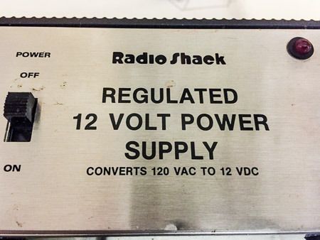
Also, recognize that the “go to” resistor for train engine headlights is 1,000 ohms @ 1/4 watt. If the engine runs up to 24 volts, that’s 22 milliamps. Also, at 24 volts, that’s ~1/2 watt. If the train runs at 12 volts, that’s 10 milliamps, but you can still see the headlight in daylight.