I haven’t used the Sparkfun boards, but I’ve been using the ESP32 dev boards from EZSBC for a few years. I like them because they expose all the IO pins of the ESP32.
https://www.ezsbc.com/product/esp32-breakout-and-development-board/
I haven’t used the Sparkfun boards, but I’ve been using the ESP32 dev boards from EZSBC for a few years. I like them because they expose all the IO pins of the ESP32.
https://www.ezsbc.com/product/esp32-breakout-and-development-board/
Bob,
They do have the uFL version I need. Have you ever programmed them with the Arduino IDE?
If so, what board files do you use, ones from ezsbc, or ???
Steve
Using the Arduino IDE, yes, and have the "esp32 by Espressif Systems installed in the board manager
Bob,
I noodled around on the ezsbc forum and found my answer, They use the Espressif tools:
https://github.com/espressif/arduino-esp32
Steve
Steve said:
Hi,
I see that all the DCC++ posts are getting a little stale - so I thought I’d start one on: DCC++EX.
They picked up where DCC++ left off They have created a very nice website for support.
I am converting my deadrail system from MTH DCS to DCC++ to allow control with JMRI Dispatcher.
Here’s my DCC++EX progress so far:
Steve,
Thank you for posting this. Your project may be the stimulus I need to resurrect an old project.
About 18 months ago I built a DCC++ system that looked very similar to yours except that I had the Pololu motor shield.
I was using Engine Driver on my phone, with the signal being track fed. The idea was that the system would be made more compact,
and used as on-board for Dead Rail.The system worked great while it was track fed. However, shortly after that when some modifications were made, everything stopped working. After many hours of ineffective effort, I got frustrated
and put the whole thing in a shoe box and stuck it on a shelf in the garage. I put DCC++ completely out of mind until now.I will be following your progress and perhaps go find that shoe box…
John
John,
I love your thumbnail! When I was just about that age I had one of those large drycell batteries with screw down connectors that had gone dead. I figured I could put more juice back in by attaching a lamp cord to the terminals and plugging it into an outlet. That experiment started with a LOT of sparks & blown fuses, and finished with a trip to the woodshed.
Steve
(https://www.largescalecentral.com/externals/tinymce/plugins/emoticons/img/smiley-tongue-out.gif)Steve,
a disclaimer, the photo is not me but:
I’m also guilty at about the age of 5 of sticking a hairpin in a car cigarette lighter socket…I had a crinkle shaped scar on my right index finger for years.
This along with the above resulted in immediate punishment that was far worse than the electrical damage !
I’ve gotten my Sparkfun ESP32 ThingPlus converted to being a WiFi server via AT commands.
I haven’t attached it to my DCC++EX station yet as I am rebuilding the perfboard shield to better organize the connectors. But I’ve tried a number of different AT commands and they seem to work:
AT+CIPSTA?
+CIPSTA:ip:“10.11.12.86”
+CIPSTA:gateway:“10.11.12.2”
+CIPSTA:netmask:“255.255.255.0”
I can see it from the network:
$ ping -c 3 10.11.12.86
PING 10.11.12.86 (10.11.12.86) 56(84) bytes of data.
64 bytes from 10.11.12.86: icmp_seq=1 ttl=255 time=22.3 ms
64 bytes from 10.11.12.86: icmp_seq=2 ttl=255 time=44.2 ms
64 bytes from 10.11.12.86: icmp_seq=3 ttl=255 time=66.0 ms
Now I can use an external antenna via the Thing’s uFL connector.
Steve
Bob McCown said:
Nice. I have a DCC++ arduino going, but haven’t converted over to DCC++EX yet, due to (last I looked) support for the motor board that they recommended for DCC++. I will get around to it eventually, but there are so many projects on the plate right now.
Following up on myself here, I got DCC++ EX working on my Arduino and Pololu shield. What they don’t tell you is that DCC++EX is not a direct replacement for DCC++, and the mods that you had to do to the motor shield for DCC++ are unnecessary. I added some jumpers to the motor shield, and it now works. Now back to figuring out the throttle. (which I will document in another thread when I get it working)
Bob,
Info please … I have 3 or 4 different Pololu shields that I would like to try…
Which specific Pololu shield are you using?
What jumpers did you use?
tia,
Steve
I have the MC33926 shield. The original DCC++ instructions had you add jumpers, and cut some traces on the board. I had to undo these changes, basically reverting it to stock. So, a stock board should work right out of the box. All I did was set the board type in the config.h file.
Bear with me, this will be a bit lengthy. This post will document the procedure I used to free up PWM capable pin11
for use with a 3rd alternate motor board.
Problem:
To use “high precision” timing you need to use one of pins 11, 12 or 13 as they are the only PWM capable pins
available to TIMER1. The arduino motor board uses pin 12 for the main track PWM, and pin 13 for the programming
track. Unfortunately it uses pin 11 to control power to the programming track. To be able to have a station setup
that can use both the arduino channel A or an alternate motor board I needed to free up pin 11 for PWM control of
the alt. board.
Solution:
I am placing a Mega form-factor perf shield between the Mega and the motor board to hold additional circuitry
and connectors to peripherals such as the LCD, Wifi, diag port, as well as the alt motor board(s). I modified
the stacking pin connectors used for pin 11 to route pin 11 from the Mega to the alt motor board connector,
and route pin 2 from the Mega to pin 11 of the arduino motor board.
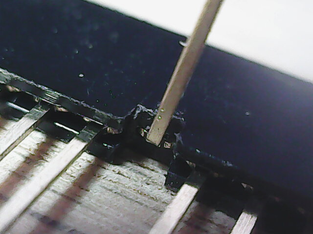
The first step was to modify a 10 pin stacking connector so that pin 11 didn’t connect to pin 11 below it,
but instead was bent to one side to provide an isolated connection point. I pulled out pin 11, then cut the plastic
on both sides of the bottom. The pin was bent sideways at 90 degrees as close as possible to the wide upper
portion then re-inserted:
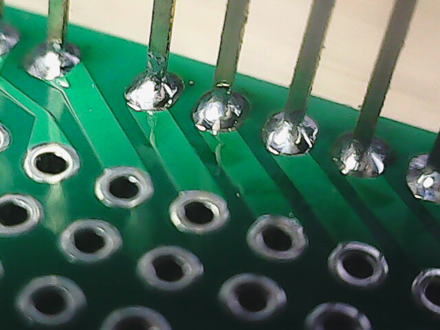
Next I added a pin to re-establish connectivity from the pin 11 on the mcu. I placed a 3 pin section of stacking pins onto the
perf shield with the center pin in the pin 11 hole. Soldered that pin from the bottom side and then removed the plastic
shell along with the 2 un-soldered pins. I cut the top clamp fingers close to the board and then filed the top smooth:
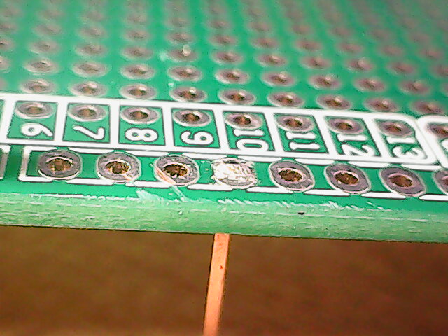
Note that the perf boards pin connection points are not aligned with the pins, DON’T BE FOOLED:
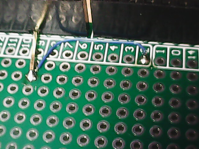
Now the modified connector is installed onto the perf board and soldered in place:
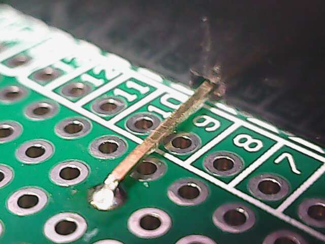
Check the clearance between the 2 pins:
Finally you tack the arduino motor board’s pin 11 to pin 2 on the perf board (which comes from the arduino mcu):
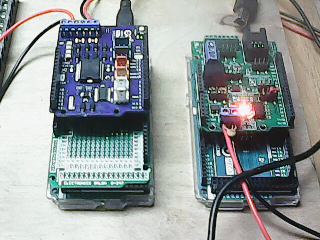
The board on the left is the station arduino with the perf board and arduino motor board installed:
Then you modify the source code to:
#define MY_STANDARD_MOTOR_SHIELD F(“MY_STANDARD_MOTOR_SHIELD”),
new MotorDriver(3, 12, UNUSED_PIN, UNUSED_PIN, A0, 2.99, 2000, UNUSED_PIN),
new MotorDriver(2, 13, UNUSED_PIN, UNUSED_PIN, A1, 2.99, 2000, UNUSED_PIN)
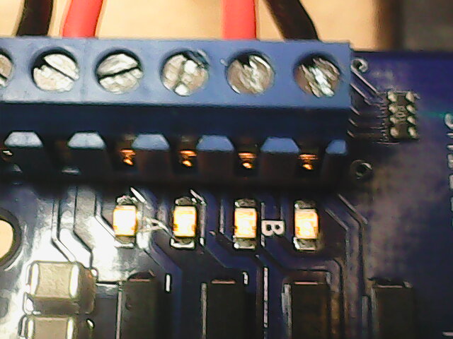
Note the change for the programming track power control from 11 to 2. After loading the new code
and turning on power with your throttle you should see the B channel (programming track) status
LEDs on the arduino motor board turn on:
Now on to building the connector portion of the perf shield!
Steve
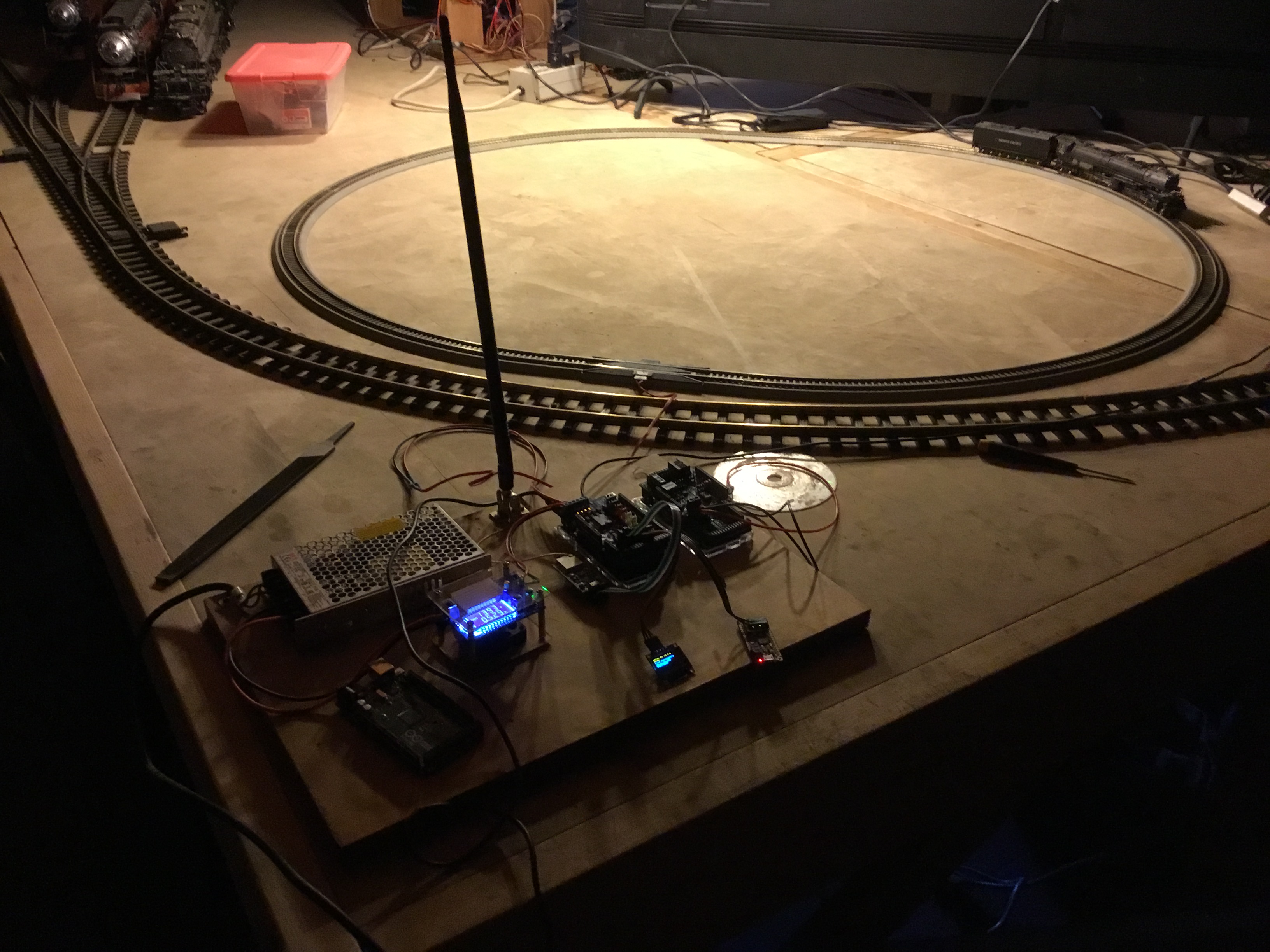
I finished the shield:

Left to right, the 1st connector is for a diagnostics serial port.
The 2nd is for the ESP32 Wifi module.
The 3rd is for the OLED display.
Below them is a 2x18 pin socket for alternate motor boards.
Those motor boards will look something like:

For Wifi, I’m successfully using both the SparkFun ESP32 ThingPlus and the ezSBC ESP32 breakout board. Here are all 4 sections:

I found a Feather M0 AdaLogger in my junk box so I connected its serial1 port to the shield’s diagnostics port:

I loaded a very simple program that echos anything coming from its serial port to its USB port.
Then I connect to it with minicom and see all diagnostics generated by DCC++EX.
Note that this Feather has an onboard micro sdCard holder, so when it goes into a DeadRail system I will extend this program to write all diagnostic messages to the sdCard. Thus I will have a complete log of any issues that occur while running the choo-choos outdoors
I have the DCC++EX code running on my Adafruit Grand Central!!!
Headlight on:
L:003 FL:0 F1-F4:0000
L:003 F-STP
L:003 FL:1 F1-F4:0000
L:003 F-STP
Bell:
L:003 FL:1 F1-F4:0000
L:003 F-STP
L:003 FL:1 F1-F4:1000
L:003 F-STP
Horn:
L:003 FL:1 F1-F4:0000
L:003 F-STP
L:003 FL:1 F1-F4:0100
L:003 F-STP
Throttle up from 0mph to 65mph:
L:003 FL:1 F1-F4:0000
L:003 F-STP
L:003 FL:1 F1-F4:0000
L:003 F-006
L:003 F-006
L:003 F-007
L:003 FL:1 F1-F4:0000
L:003 F-007
L:003 FL:1 F1-F4:0000
L:003 F-007
L:003 FL:1 F1-F4:0000
L:003 F-008
L:003 F-008
L:003 F-009
…
L:003 F-065
L:003 FL:1 F1-F4:0000
L:003 F-065
L:003 FL:1 F1-F4:0000
L:003 F-065
===
Next step is to haul the electronics out to the train room and see if it controls my BigBoy.
Steve
Nice progress.

Built a connector shield for the new Adafruit Grand Central setup. This one was simpler than the Arduino Mega version.
As everything is now 3.3V I didn’t need a bank of level converters. And the fact is that the SAMD can’t put an appropriate TCC/PWM behind the 2 pins the Arduino motor board uses for DIR I couldn’t use the pin11 to pin2 hack. I didn’t place this one between the mcu and motor board. Instead I cut the end off a Mega sized breadboard and placed it at the same level as the motor board. I also brought up the end-connector (ie. the 36 pin 2x18) with stacking connectors. That will give me ample pins for any extensions I want to work on. This new connector provides a port for an OLED display, the ESP32 Wifi board and an Adafruit Feather M0 diag mcu.
Got the Feather version working,
Output of my ARD board:
L:003 FL:0 F1-F4:0000
L:003 F-STP
…// start engine:
L:003 FL:0 F1-F4:0010
L:003 F-STP
…
L:003 FL:0 F1-F4:0010
L:003 F-STP// headlight on:
L:003 FL:1 F1-F4:0010
L:003 F-STP
…
L:003 FL:1 F1-F4:0010
L:003 F-STP// bell on:
L:003 FL:1 F1-F4:1010
L:003 F-STP
…
L:003 FL:1 F1-F4:1010
L:003 F-STP// bell off:
L:003 FL:1 F1-F4:0010
L:003 F-STP
…// horn on:
L:003 FL:1 F1-F4:0110
L:003 F-STP
…// horn off:
L:003 FL:1 F1-F4:0010
L:003 F-STP
…// throttle up:
L:003 FL:1 F1-F4:0010
L:003 F-STP
L:003 F-006
L:003 F-006
L:003 FL:1 F1-F4:0010
L:003 F-008
L:003 F-008
L:003 F-009
L:003 FL:1 F1-F4:0010
L:003 F-010
…// to 48mph:
L:003 F-049
L:003 FL:1 F1-F4:0010
L:003 F-049
L:003 FL:1 F1-F4:0010
…// stop:
L:003 FL:1 F1-F4:0010
L:003 F-STP
At this point I trust the ARD enough to go forward without a choo-choo test. The whole breadboard thingy is a rats nest of wire & probes, too fragile to move to the train room and expect nothing to go south.

I’m working on modifying the Adafruit Triple FeatherWing breadboard to be specific to this project: pull a bunch of the unneeded breadboard stuff off, add traces from my schematic, and a few connectors. OSHPark quoted me $28 for 3 boards - not bad!
Steve
Cool. I like the idea of the logging.
I got an IRF 3205 motor board in the mail over the weekend. Rated to 15 amps, that should work out well for the RR. Just have to figure out where I put my 20a 18v supply…
Bob,
In the lower left of the pic is a Cytron MD13S motor board.
Its rated for 10 amps. Along with that I still need to add an ACS725 based 10amp DC current sensor.
I need 5 amps max for my BigBoy, so this pair give me 100% safety factor. And both are 3.3V so no data level conversions required.
Steve