Large Scale Central

Adding battery power & r/c to Accucraft K-27

I have posted this also on the UK based GSC site, that a number of LSC members frequent, but I thought as the loco in question would be more numerous in the location this forum sees as home it might help to post here too. I’m really looking for this information to give me the confidence to dove into the job Two bites at the apple.

I have an older version track powered Accucraft K-27, the one with the right rail pickups only on the 4 tender wheels and the left only on the loco’s 4 driving wheels. The loco and tender are electrically insulated from each other. Apparently this was once a common practice with “all metal” construction model locos. Later versions of the Accucraft model picked up current on both sides of the loco, all wheels. The loco has a functioning Sierra Soundtraxx sound card fitted. Most sounds are voltage activated but the chuff and a couple of other sounds are reed switch activated.

I have the published manuals for both the loco and the sound card. The sound card’s has a full wiring diagram for its own installation but the loco does not. I have searched the web for the latter but to no avail. I did find an old Garden Railways article, authored by Tony Walsham (who posts here too), but it is not clear as to how he (re)arranged the power supply to the motor and isolated the pickups on this specific loco type when doing a similar conversion some years ago.

As I understand it replacing the track pickups’ voltage inputs to the sound card is fairly simple - replace input from track pickups with those from one of the 2 pairs from the electronic speed controller (esc). What I am not sure about is how to isolate the motor (and possibly chassis too) from track induced voltage inputs and how best to attach the esc voltage output to the motor. There is a terminal block, accessible under the ashpan, where a number of wires coalesce for power distribution on the loco itself. I have not investigated these yet

Questions - Am I right in the assumptions I have made so far and how do I isolate the track pickups on the loco (tender is self evident) and correctly connect the motor to the esc without ripping the loco to bits ? Your assistance and suggestions would be most welcome.

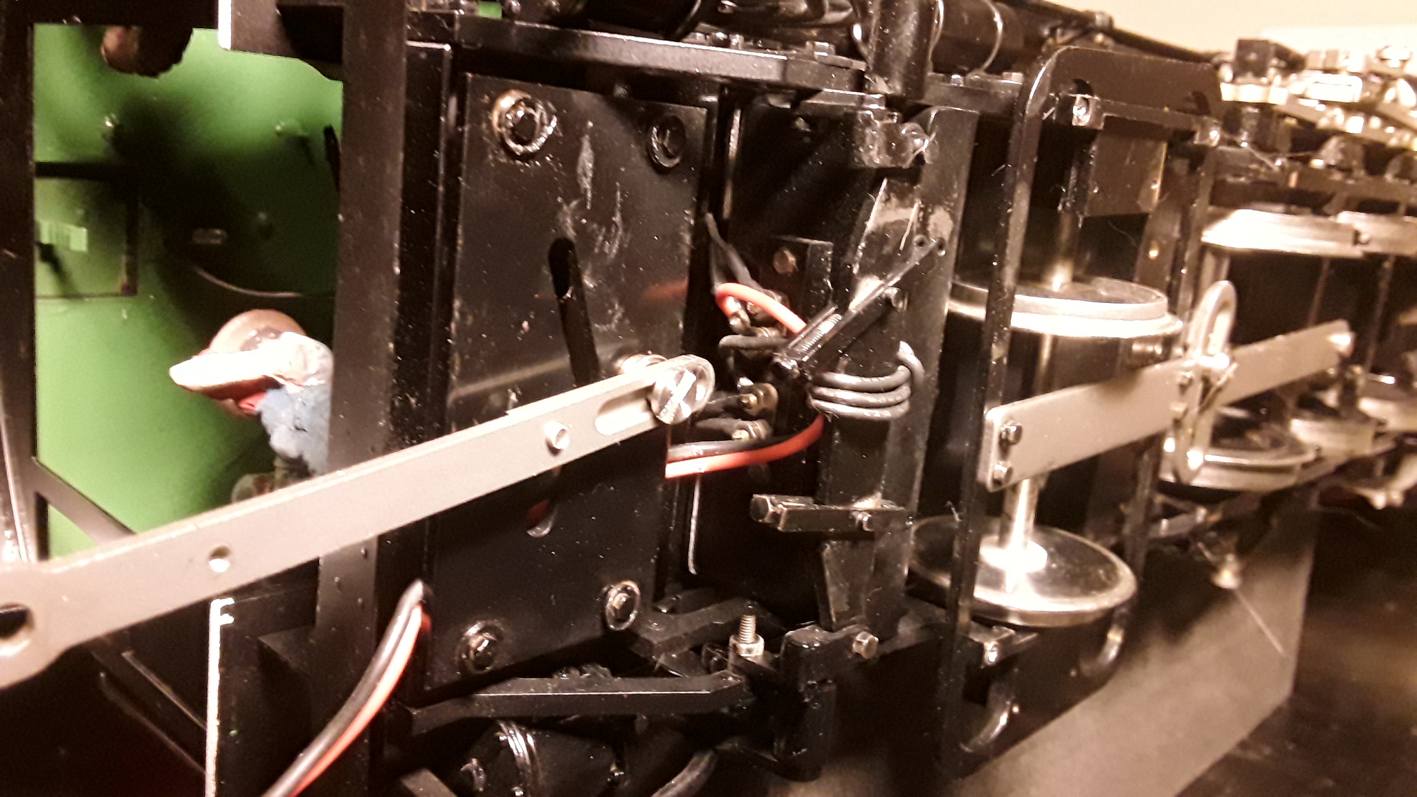
A picture showing the terminal block under the loco’s ash pan. As a point of note I have acquired all the conversion gubbins from UK company Fosworks - A Cobra high frequency 6 - 24v speed controller (made for DC motors), 14 cell AA NiMH battery pack with 5 amp fuse, Omni Tx-2.0 transmitter (nice little palm of hand unit), Omni RX-2H receiver and assorted other parts for charging and wiring.

“The sound card’s has a full wiring diagram for its own installation but the loco does not. I have searched the web for the latter but to no avail. I”

google “bachmann k27 schematic” you will wind up with what you want, it’s also on my site… if you went there:

LS trains >>> motive power >>> Bachmann >>>> K27

Greg

A C C U C R A F T

O O P S… thank you Mr. Radder!

sorry! The wiring in them is not only hard to follow from the schematics I have seen, but usually the schematic is not accurate. I’ve wired a few Accucraft sparkies… found the wiring diagrams weren’t worth the paper it was printed on.

I would try to ascertain if either (or both) of the chassis (loco and tender) are “hot”, i.e. connected to any track pickups and/or motor leads. An ohmmeter is your friend.

Greg

I have a multimeter - which bits do I touch and what readings am I looking for ?

P.S I should have checked here before my response on GSC

First I would ascertain how the wheels are insulated. Wheels or axles.

You are going to trace wire using the Ohm setting. When both probes are on a continuous circuit the meter will move. Touch the probes together to see the meter’s response.

This will allow you to find out how power gets from the rims to the motor.

Happy hunting.

Yes, you should have checked here first. At least Jon kicked me in the butt more politely.

Check my web site under the Accucraft/AML … the K4 wiring page… easier than retyping it all here. Some tips and reinforcement for the advice given earlier.

Greg

Greg - I had already looked at the K4 page on your site but that loco (and the other electric Accucraft you feature 0-6-0 switcher) does not have the the same pick up arrangement as in the K-27 in my possession. To my novice eyes the wiring schematics (or diagrams as they are labeled) to not work for the loco I have. I am trying to get definitive information as to this Accucraft K-27’s wiring so as to minimise risks of frying a lot of expensive (to my pocket) kit. I though one of the purposes of these forums was to be able to seek even basic advise without fear of being ridiculed and patronized - a “safe space” so to speak.

As to the any lack of politeness of my response to your somewhat arrogant and patronizing, never mind totally off the mark response, an omission yet again repeated, I am happy to print it here and let others judge my impoliteness. Whole thread here https://www.gscalecentral.net/threads/converting-accucraft-k-27-to-battery-r-c.312015/

Unredacted/Not edited text here -

Greg Elmassian said:

can’t find wiring diagram? Well, the term is schematic for electronic engineers

…google “bachmann k27 schematic”

you will find it…

(and it’s on my site as well as other places)

Been there for years."

Greg

Greg -

The loco I have is an Accucraft not a Bachmann make and as an early version has a different pick up arrangement to a regular “plastic” K-27 or even later model Accucraft K-27 and that affects the wiring schematics .

Not that I wish to alienate one who is so generous and erudite in their responses, and from which I have benefitted, but as you are so fond of reminding those who miss the mark when responding to posts - please refer back to my initial post :)

But I am very grateful for your offering the term “schematic” as providing the possibility for better/additional search results to that of “diagram”. Max

General note - Try not to be patronising in your responses, especially when you have got the wrong end of the stick yourself. It may cause the issue, as you may be seen by other members of this community as one of the “fonts of all knowledge in these things”, that others will think the original poster has either been a bit remiss in their initial research or assumptions before posting or a complete numpty (I’ll personally take the 5th, as some might say, on that last one).

I see you delight in poking me again for something I apologized on 2 continents for… good for you… I hope at least it makes you feel better doing something mean on purpose…

The point was that in my experience, from what I have worked on and the countless people I have helped, the “factory” schematic of Accucraft and AML locomotives is almost always not correct.

The point was NOT that the schematic I linked to was appropriate, but it was an EXAMPLE… I’m afraid after reading past the personal jabs, you did not get that point, since you pointed out the schematic was not appropriate for your loco. That is the logical process I came to that makes me believe you did not get it as an EXAMPLE. This is the only reason for my post, to continue to try to be helpful.

Wires are swapped, color codes ignored, components missing, and worse major wiring things changed, like different lights assigned to different voltages and circuits.

So my advice, is look at the schematic, and note that they use several circuits, different voltages and from me, that often there is a voltage regulator “hidden” somewhere.

My further advice is you can either try to figure it out with a voltmeter and basically determine the schematic yourself, or basically rewire the loco to a known state, i.e. run the LED and motor and track pickup wires back through the plug to the tender.

I hope for your sake that you encounter what I did, that there are many “spare” contacts on the connector, thus being able to control everything and have separate wires from the loco to the tender is somewhat easy, at the worst case possible.

If you need further help, some pictures might help, but it seems that Accucraft and AML had a maddening habit of choosing wire color variety like Henry Ford and the Model T colors, black.

Greg