well, Todd first broke up the problem in manageable pieces, like:
trains will always face the same ways on the end sidings so that the postion of the engine and reed switches need not change from one end to the other (simplifies things a bit)
using one EPL on each turnout and only throwing two turnouts at a time per reed switch with six reed switches.
then we had some back and forth communication like this:
(the > marks Todd’s lines)
I will only place reed switches on the four pier sidings, one on the top siding, one on the bottom siding, and two on each of the interior sidings, so train length won’t be a problem here. There are no reed switches along the “by-pass” siding.<
that did not occur to me.
Also the by-pass siding will not be double insulated (or insulated at all) from the four pier sidings, and everything left of the two mainline turnouts will undergo simultaneous polarity changes.<
once you mention it, it sounds logical.
In fact, the entire left side need not be insulated from the mainline at all so long as trains remain parked on the mainline (and its sidings) when operations along the by-pass siding occur (but we’ll insulate it anyways).<
yes, because as i see it, there will be trains still moving on the mainline, while a train at the harbor will begin to back up.
Each of the two “pier turnouts” will use one side of the 030 dpdt to route power to that siding when the turnout is thrown that direction. One of the two by-pass turnouts will be wired with the 030 as a dpdt reversing switch such that when the by-pass is selected the current to the left side of the railroad is reversed …<
yes, understood.
The heart of the system is in the the EPL on the other by-pass turnout that will be used to route the current from the reed switches so that they are not activated at the wrong times. …<
do i understand that right? you want to interrupt some cables between reed and turnoutmotor at times?
Yes, I’m thinking that you may have to.
When the train pulls onto a pier siding it passes over the reed switch and “trips an action.” Later, when the train pulls out of that siding, you don’t necessarily want that action tripped again, but the engine magnet will still pass over the reed, so you need some way to ignore it. If the trains were to go in a loop, rather than back out, this would not be a concern because you would only pass over that reed one time and trip the appropriate action once.
This is the point where the wiring is giving me a headache and I needed to get away from it and work on the railroad, but I do believe that we can do it.
Maybe you can see where I’m going from here?<
i think, i begin to get an idea, what you are up to.
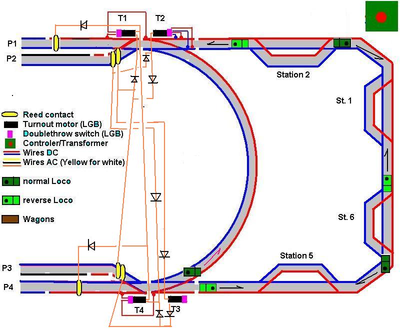
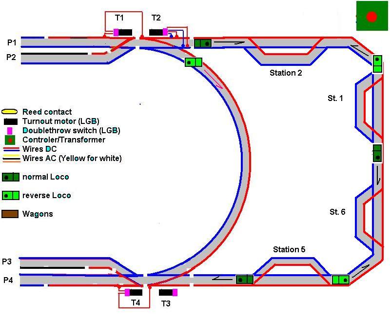
first solution by Todd:
Number the piers from 1 to 4 from north to south (P1, P2, P3, and P4).
Number the turnouts from 1 to 4 going clockwise and starting at the northwestern turnout (T1, T2, T3, and T4). Each turnout has an 030 DPDT. Assume T2 is used as a reverser for the "left side" when it is thrown to the curved position. T3 will be used for reed switch routing.
The Piers are only “live” when the turnout points to them using 030s (single gapped) mounted on T1 and T4. Double gaps are used east of the siding turnouts.
Here we go.
Train pulls into P1 and trips a reed switch that throws T1 and T4 to the interior pier sidings (P2 and P3).
The train on P2 leaves clockwise to the main line and it, or another, eventually comes to P3.
P3 has two reed switches (your imposed limitation). As train nears the end of P3 the first reed it comes to throws T3 to the curve and T4 to the exterior position (P4). This cuts the power to P3 and throws the EPL that will be used to route the reed switches. The second reed switch throws T1 and T2 and the train sitting on P1 comes to life just as the current is reversed.
The train on P1 backs through the siding to P4. This trips a reed on P4 that throws T1 and T4 to their inner positions. This kills the train on P4 and brings the train sitting on P3 to life and it backs through the siding to P2.
When the train pulls on to P2 it passes two reeds. The first throws T3 to the straight and T1 to the exterior position (P1). This cuts the power to P2 and throws the EPL that will be used to route the reed switches. The second reed switch throws T4 to the straight and T2 re-reversing the current and the train sitting on P4 comes to life and heads back out to the main line.
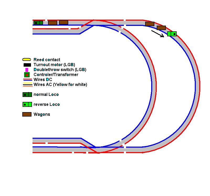
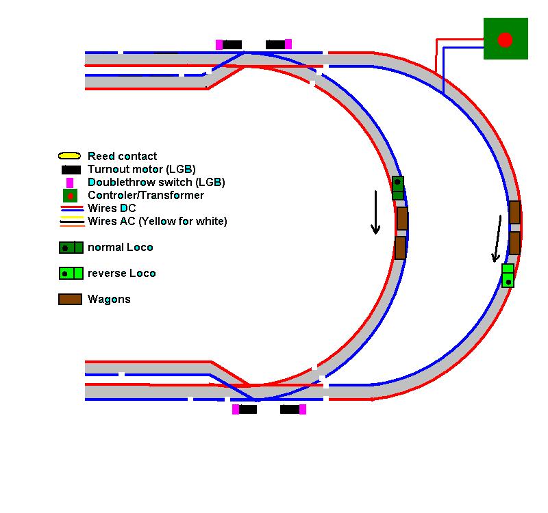
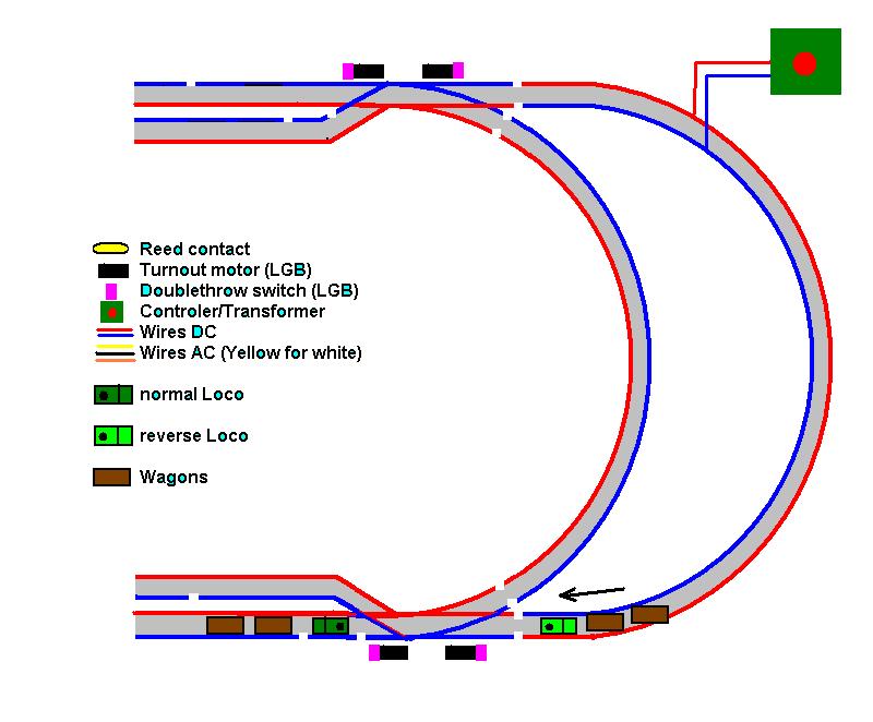
that would be this, if i choose the right pic now:
but there were some preopucations left.
as set up, the harbor, with its two “stations” would set the pace for the whole layout. i didn’t think, that would work. because there are up to 80 foot of track between the other stations.
if the shortest distance (the small loop in the harbor) had set the pace, it would have caused havok on the other sections.
another possible problems could have been, that the trains going into P2 or P3 might come to rest exactly above the second reeds, thus frying them with their magnets.
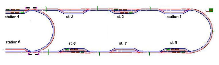
i revised my plans, including all stations. (P1 and P2 together would be station3. P3 and P4 would be station 4)
the harbor, with its four piers is replacing two stations with passing sidings. so for the whole picture, P1 and 2 are station 3 and pier P3 and P4 are station 4.
the whole layout would know only three situations:
- two trains (of opposing polarity) in every odd numbered station.
- one train on every track-section between stations.
- two trains (of opposing polarity) in every even numbered station.
(the section between stations 5 and 6 is the longest, therefore the trains on this section would have to trigger everything else.)
then Todd solved the riddle of the Sphynx.
The EPL on T3 that was to control the reed switches does not have enough contacts or positions to satisfy all possible scenarios. So, we are going to remove that EPL and just use the turnout as an electric turnout and it will not be routing power.
So, how do we get the reeds to ignore the magnets when necessary, and how can we keep a train from parking over a reed and causing its demise?
We need to add two more turnout motors connected to EPLs and four more reed switches. The reeds will be placed immediately west of the other reed switches (the one on P1 and P4 and the two on P2 and P3). We really want these switches as close together as possible and you should physically glue the two or three reed tubes together, rather than have them in seperate housings. This will ensure that all are tripped and lessen the possiblity of parking over them. (But that will no longer be an issue.)
The new reed switch on P1 and P4 will control an 010/030 and we only need to use one set of contacts of the EPL. The reed switch on P1 routes through one contact of the 030 and the reed switch on P4 routes through the other. The common contact actually allows the current to flow to trigger the turnouts. So when the train arrives at P1, the very last reed it encounters throws the 010/030 to the other side and the reed switch on P1 is cutoff until the train reaches P4 and triggers that reed, that cuts off the P4 reed off and brings the P1 reed back on line so that they always alternate.
We do the same thing for P2 and P3. But in this case, we use both sets of contacts on the 030. One set of contacts will cut off the first reed along the siding and the other set of contacts will cut off the second reed along the siding, turning the control over to the reeds on the complimentary pier as was done on P1 and P4.
Everything will still play out as I previously noted.
BTW, when the train leaves P1 eastbound around the mainline, it would not be the train that pulls into P4. That would be the last train in the sequence headed in that direction so it should not be that long a wait.

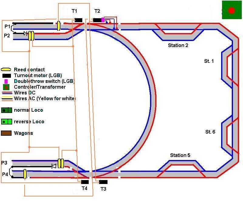
After that, he found Another Way to Skin a Cat
Just to show that there is always more than one way to do things, here is a completely different, cheaper, solution that solves the same problem and accomplishes the same movements. I’m sure that there are other ways this could also be done, but this one was keeping me up (note the time).
Number the piers from 1 to 4 from north to south (P1, P2, P3, and P4).
Number the turnouts from 1 to 4 going clockwise and starting at the northwestern turnout (T1, T2, T3, and T4). Assume T2 has an 030 and is used as a reverser for the “left side” when it is thrown to the curved position. Other than for the turnouts themselves, no other turnout motors or 030s are required.
P1 has a single gap in the northern rail where we want the engine to stop. There is a reed switch located just west of this gap that throws T2 and T3 to the straight (mainline setting). This sets the reverser in the "normal" mode.
P2 also has a gap in the northern rail where you want the engine to stop. But in this case, we will span the gap with a diode, just as if we are setting up a reversing unit’s end of track. There is a jumper wire that goes from this insulated section of track on P2 to the insulated section on P1 beyond its gap.
P2 has two reed switches placed just east of the diode. The westernmost (outer) reed switch throws T1 and T4 to the straight positions for the trains to enter P1 and P4. The easternmost (inner) reed throws T1 and T4 to curved positions for trains to enter P2 and P3.
P3 also has a gap in the northern rail with a diode where you want the engine to stop. But in this case, the diode faces in the other direction. There is a jumper wire that goes from this insulated section of track to the insulated section on P4 beyond its gap.
P3 also has two reed switches placed just east of the diode. The westernmost (outer) reed switch throws T1 and T4 to the straight positions for the trains to enter P1 and P4. The easternmost (inner) reed throws T1 and T4 to curved positions for trains to enter P2 and P3.
P4 has a single gap in the northern rail where we want the engine to stop. There is a reed switch located just west of this gap that throws T2 and T3 to the curved (bypass setting). This sets the reverser in the "reversed" mode.
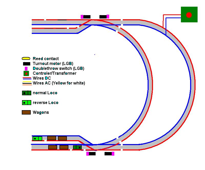
Lets’ say that initially a train is sitting on P1 behind the gap at the ready
So here we go.
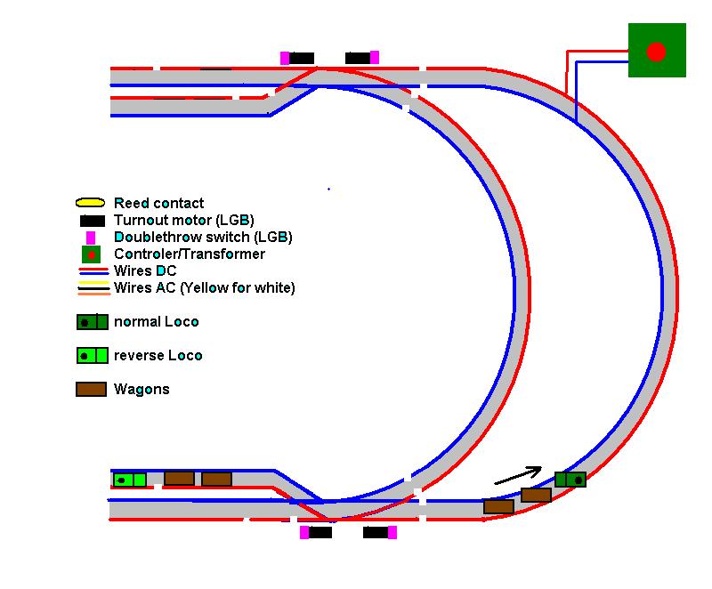
User toggles the turnout and train pulls into P2. As the train passes the first reed switch T1 and T4 are toggled to the inner positions (P2 and P3), then, as the train toggles the second reed it puts the turnouts to the outer (P1 and P4) positions. The engine then passes the diode and stops.
As the engine is passing the diode, its wheels span the gap and power can flow to the isolated section. This also sends power to the train sitting on P1 through the jumper wire. Because this train runs in the opposite direction it takes off eastbound by itself while toggling the reed setting T2 and T3 to the main line (where they already were in this case).
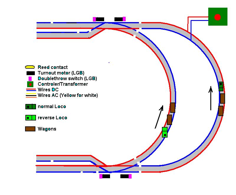
This train (or another) comes around and enters P4, because that’s how the turnouts were left from the train on P2. It crosses the gap and stops, AFTER it trips the reed. (More on this in a bit.) This throws T2 and T3 to the by-pass position and reverses the current to the left side.
Now the train that is sitting on P2 comes to life because current can flow through the diode. This train starts to back out and first encounters the western reed throwing the turnout to the outer position (P1 and P4), then to the eastern reed throwing the turnout to the inner (P2 and P3) position and the train backs around the bypass to P3.
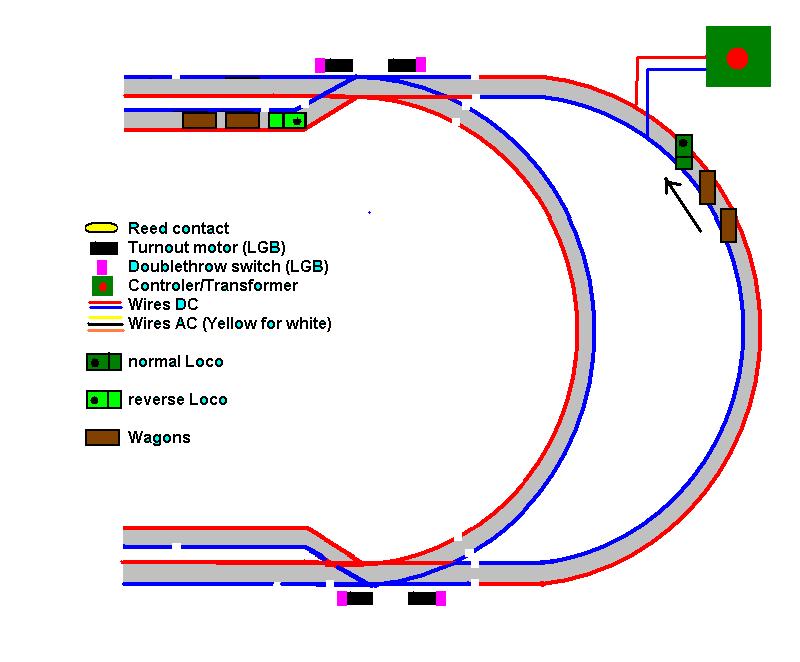
On P3 it encounters the eastern reed throwing the turnouts to the inner position (P2 and P3) then the western reed throwing the turnouts to the outer (P1 and P4) positions then crossing the diode and stopping.
As the train is passing the diode, its wheels span the gap and power can flow to the isolated section. This also sends power to the train sitting on P4 through the jumper wire. Because this train runs in the opposite direction it takes off eastbound by itself while toggling the reed setting T2 and T3 to the bypass line (where they already were in this case).
The train pulls into P1 and passes the gap, stopping AFTER it trips the reed, while throwing T2 and T3 back to the mainline position and re-reversing (straightening???) the current.
(This is the part I left out last night.)
When the current is set back to the normal (non-reversed) position, current can now flow thought the diode on P3. The train sitting on P3 leaves going eastbound and and first encounters the the western reed throwing the turnouts to the outer position (P1 and P4), then to the easten reed throwing the turnouts to the inner (P2 and P3) position and the train heads out to the mainline because when the other train backed onto P1 from P4, it reset T2 and T3 to the mainline as it reset the current. This train (or another) then proceeds counterclockwise around the mainline and enters on P2, because thats where they were left when the train left P3.
With respect to the reeds in the isolated sections of P1 and P4. When the train came around the mainline from P1 to P4, the current was flowing in the “normal” direction. The diode on P3 allows curent to flow in that direction and the current makes its way to the isolated section of P4 through the jumper. When the train comes onto P4 and passes the gap, the rail beyond the gap is still alive through the jumper until the train trips the reed and this reverses the current. Once the current is reversed, it can no longer make its way through the diode so the train remains dead on P4 until something spans the diode or re-reverses the current.
The same situation occurs when the train uses the by-pass to go from P4 to P1. When this occurs, the current is in the reversed state. In this state it can pass through the diode on P2, follow the jumper and make its way to the isolated section on P1. This section then stays alive until the engine trips the reed the puts the current back to the normal state and no current will pass through the diode on P2, so the train remains dead until something spans the diode or reverses the current.
Benefits include fewer parts and trains always cross reeds under power (eliminating parking over reeds). Also, there is benefit in having the diode/jumper combination in that when a train comes into P1 or P4, it looses 0.7 volts through the diode, slowing a bit before crossing the reed and stopping. Also, when a train spans a diode to release the other train, for a moment, they share current, slowing the trains a bit during their simulaneous stop/start.
Another benefit is ease of wiring, The two western reeds always throw T1 and T4 to their outer settings and the two eastern reeds to their inner settings. So the western reeds can simply be wired in parallel as can the two eastern reeds. Furthermore, T1 and T4 always throw together, either inward or outward. So these two turnouts can be wired in parallel. Now you only need one diode for the two western reeds and one diode for the two eastern reeds.
Similarily T2 and T3 always work as a pair either throwing toward the mainline or the by-pass. So they can be wired in parallel. Now we only need one diode from the reed on P1 and one diode from the reed on P4.
i like this one!
after i put it to the plan, it looks really simple.
well, as it was Todd, who came up with brilliant ideas, here a quote from him at the end of the thread:
"Yes, I fancy this one too. It’s elegant in its simplicity (…)
But it has its caveats. For example, the diodes are sensitive to polarity so you need to be careful as to the placement of normal/reversed current engines. Also, if you use lighted cars, you may need to disconnect the first truck from the lighting circuit so that it doesn’t cross the gap and let current flow to the engine.
Finally, the engine leaving from P1 and P4 must make it past the gap while the engine on P2 or P3 “stradles” the diode. So, we want to put this reed as close to the gap as possible, but far enough for the longest engine to clear the siding before hitting the reed.
I don’t think it really gets any simpler (or cheaper) than this and I would dare anyone to try to do similar movements with anything shy of computer control. (Those R/C and DCC people can eat their hearts out.)
(Don’t forget the four diodes that route the turnout current.) "
another quote from a guy, who read that thread and made the last post:
"Hi Kormy…(http://www.mylargescale.com/Providers/HtmlEditorProviders/CEHtmlEditorProvider/CuteSoft_Client/CuteEditor/Images/face1.gif) DC is great isn’t it. "
seeing that comment, made me reflect about the “power-war”
it is easier to convert locos to battery, or set up DCC, than set up a complicated DC layout. yes.
but the time those guys save while preparing the layout, they spend while running trains.
and…
… the only way, i get burnt fingers is by dozing, while i hold a cigarette.
