Been thinking on the first structure I want to build for the layout. I need a couple of bridges. I have one problem spot that is very temporary which is the lifting bridge. I never did do it right and it does not hinge correctly and causes all sorts of problems with track alignment when it get put down. So, for the first structure I think I will build my Warren Truss lifting bridge. I know this has come up before but I need ideas on how to incorporate a lifting hinge into a truss bridge. I know what it needs to do but would like to see some pictures or drawings of what people are doing.
Devon Sinsley said: would like to see some pictures or drawings of what people are doing.

Sean McGillicuddy said:
Devon Sinsley said: would like to see some pictures or drawings of what people are doing.
Very Helpful
Devon,
Your request begs a few questions to help clarify what your intent is.
-
As you know a prototype truss bridge is open structure with stringers for the ties and rails to sit on. Is this your intent in the model or will there base be a solid foundation (ie 2 x 4) for the track to run on with the rest of the structure display?
-
How long a span are we talking about? Single track?
-
What are the ends of the bridge going to be (the foundations the ends sit on, I can’t remember the proper terminology)?
-
Is it your intent for the bridge to be in the raised position when not in use?
Give me some time and I will likely have more.
Bob Cope said:
Devon,
Your request begs a few questions to help clarify what your intent is.
As you know a prototype truss bridge is open structure with stringers for the ties and rails to sit on. Is this your intent in the model or will there base be a solid foundation (ie 2 x 4) for the track to run on with the rest of the structure display? My intention was/is to have a working functional truss bridge without any additional base. With that said I will add what ever structural elements need to be added to make it functional and as trouble free as possible. One thought was to make the base out of a piece of plate aluminum so it could be easily hidden but still be the structural element upon which the track sits on. I am open here.
How long a span are we talking about? Single track? Single track 30" span.
What are the ends of the bridge going to be (the foundations the ends sit on, I can’t remember the proper terminology)? structurally the abutments are vinyl 1X6.
Here is the not so good temp.
- Is it your intent for the bridge to be in the raised position when not in use? Yes. this is just a industry siding/tip of my Wye. It will be up and locked in place except when needed. It is the only place to walk through from one side to the other.
Give me some time and I will likely have more.
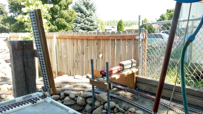
The whole section from the bench to the fence is temporary. What will be there permanently is the Howe truss bridge crossing over to a wooden structure that will serve as a tunnel of sorts with a building and the siding on top that will serve as an ice house.
There’s a secret, you need an offset hinge that lifts the rail ends away before lifting, basically the hinge points are above the level of the rails.
The angled base will go down on the baseboard that the track is on, the flat piece on the side of the moveable part…
rotate this picture 90 degrees counterclockwise…
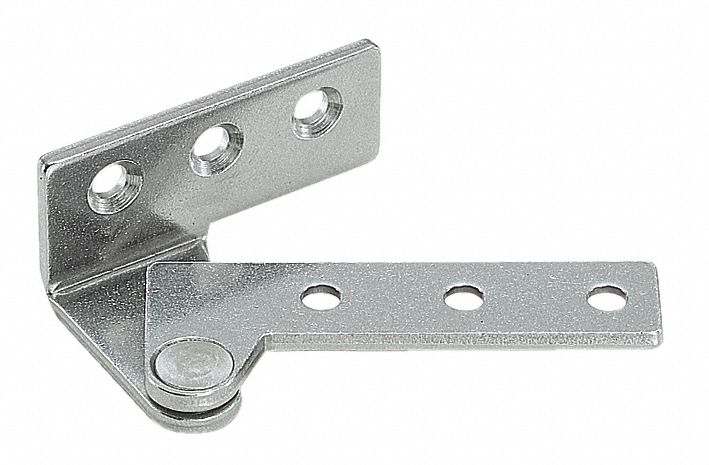
you will see that in effect the offset moves the rails apart very soon as compared to swinging.
This makes a big difference on how nicely you can make the rails fit together at the hinge joint.
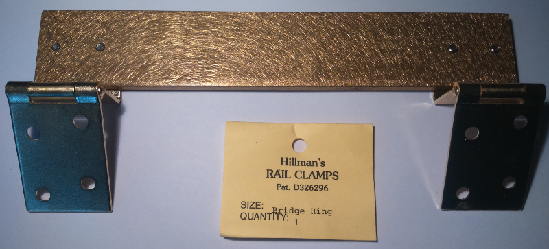
If you can find a picture of the hillman bridge “hinge” you will see it works similarly
Greg
Greg Elmassian said:
Greg
Something like this is exactly the sort of thing I envisioned needing. I am pretty sure you showed me this once before. Do you know the name of this style of hinge? Is this something you can get at a big box store.
I googled the Hillman bridge hinge and was wondering if one could just use a T Hinge bent to shape
I am generally a pretty handy guy but for some reason I am having trouble seeing how to make this work (easily) without having to fabricate the entire hinge assembly.
If I were to bend a T hinge to shape, I am thinking that the pivot point of the hinge needs to be as high or higher than the top of the rail, right, preferably higher? Then it will lift away as it is rising?
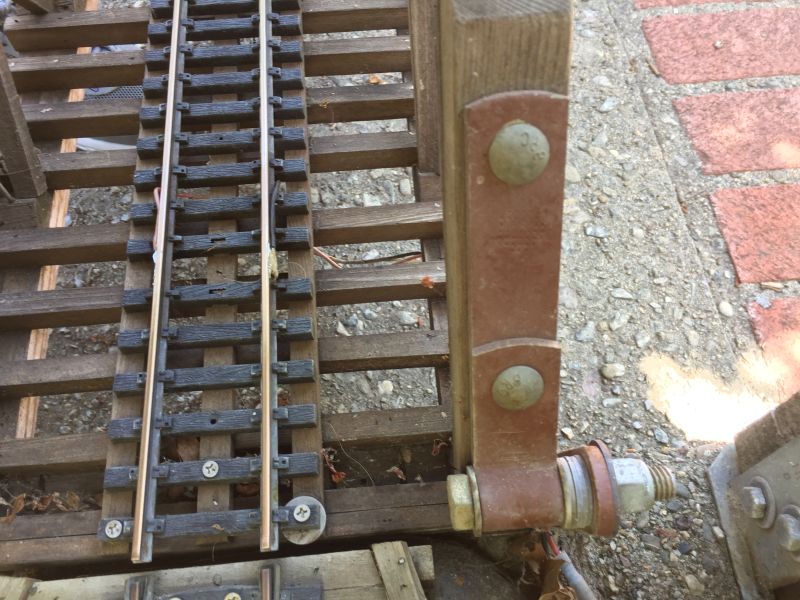
Take a look at my bridge hinge Devon, has worked for eleven years with no problems.


Dan,
I see how the bottom part of the hinge is working. Is the top part a barrel type hinge that is bolted to the girder?
Devon Sinsley said:
Dan,
I see how the bottom part of the hinge is working. Is the top part a barrel type hinge that is bolted to the girder?
That’s correct Devon I’ll try and get a photo of that later today.
I understand fully. This was the type of solution I was looking for.
Same idea, the hinge point above the rails… that’s the key…
In this case, the end of the moving part is also “beyond” the pivot point, thus making sure the rails separate before lifting, if you will.
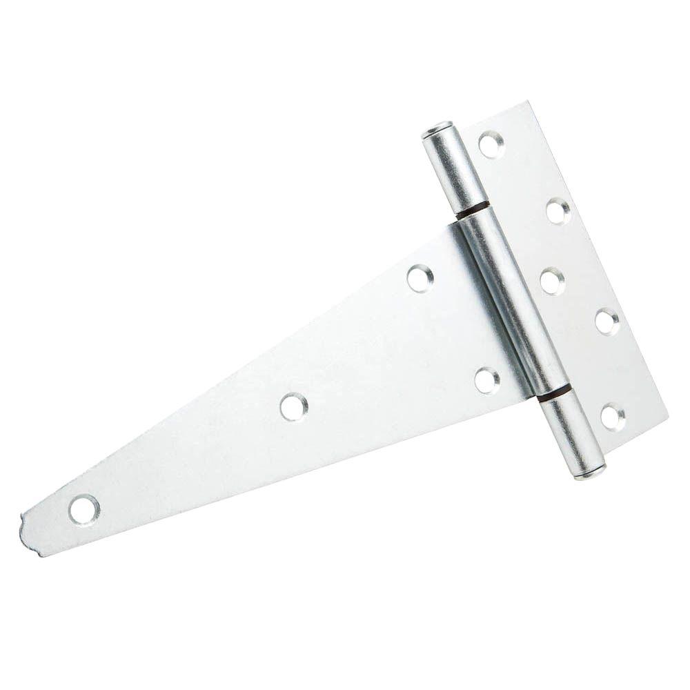
if you wanted to bend one yourself, instead of the example you showed, use something like this:
But realize then that hinge is maybe 2 inches wide, so you would have to add that width to your right of way on both sides. So not really as good as the examples above.
Greg
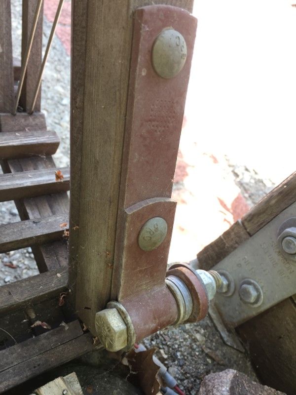
Devon here are the photos of the barrel hinge on top. At the other end of the bridge it “Keys” over a block that aligns the rails. I used Stainless bolts and washers.
Thanks Greg. I think the way Dan did it is as good as any and easy without having to get crazy fabricating things.
The one HO club I belong to folds up their balloon track module with large hinges. They look like large barn door hinges, nothing special about them. But, as has been said, the hinge pivot (barrel) is above the height of the rail-head. So when the module us unfolded, the rails butt up against each other, but when folding it up, the rails move apart instead of trying to pivot into each other.
I think that is the key. I’ve seen other approaches, like trying to bevel the ends of the rails, but in my experience, that causes even more alignment issues.
At the other end of the bridge, where the hinge “isn’t”, a nice large “alignment pin” on the underside of the bridge, and a “socket” to the “ground” really helps ensure precise and consistent/repeatable alignment of the rails.
I find the method employed by Dan, for his lift bridge, to be first class. It is tried and tested - eleven years in situ he said.
I don’t have a lift bridge at present but have often considered installing one rather than the existing fixed bridge I have. One thing you learn quickly in garden railroading is the need, ideally, for strong, lasting structures particularly if you get visitors, including children and animals (dogs in my case). Dan’s lift bridge seems to fit all those requirements.