For those of you that have made your own drive and side rods… Could you post some pics and a brief description?.. I need some more ideas. I picked up some brass stock and Styrene tonite and want to get this “party” started LOL… Thanks…
Travis,
Main and side rods can be made using only a heavy soldering iron, files, and a drill press (assuming brass rods). The following description is an old scratch/bash builders technique before some of the equipment available today was affordable for the hobbyist.
Step one - cut the strip to slightly longer than the total overall length of the rod. Solder the two strips together using the minimum amount of solder. It will work better if you have clamps (spring steel alligator clips available at an office supply store work well) to hold the pieces tightly together.
Step two - Layout the shape of the rods and carefully locate the centers of the drive pin holes on the top strip. Carefully file the outer shape of the rod keeping the file as perpendicular to the face of the strip as possible. VERY carefully drill the first pilot hole to locate the pins. I recommend as small a drill bit as the drill chuck will hold. Increase drill sizes .010 - .020 at a time until you have drilled the desired size hole for the pin.
Step three - Heat and separate the two strips being very careful to not bend them. This can be a tedious task, but well worth it in the long run. Once separated, remove as much of the solder as possible using a solder wick braid (available at Radio Shack - if you still have one). Once this is complete, use a single edge razor blade or the back edge of a #11 X-acto blade to carefully scrap the remaining solder off the rod.
This process assures that each pin hole is located the same on each side rod, and the stroke length of the drive rod is the same.
Unfortunately I don’t have any suggestions for using styrene for the rods.
Good luck Travis, keep us posted.
Bob C.
I cut small sections out of brass tubing for bearings on the crank pins. The tubing fits on the pin with just a little bit of play to it. Not sloppy, but not so snug so that it could bind. Then I fit a piece of flat bar styrene between the bearings, and then built up the ends around the brass bearings with smaller strips. One below the bearing and one above it, with a small piece on the back end. This boxes in the bearing and helps attach it to the rod. The upper and lower styrene parts extend along the rod a short distance to make sure they bond well to the rod.
When I was building my Mikado, I used brass rectangular tubing and the ends from existing gear from the Annie.
At the top is the “Original” from my Aristo Pacific. Next is the side rod I got from Barry’s Big Trains - it’s solderable. Final shot shows the tubing connected to the ends.

A view of the two pieces.
Travis
What are you thinking of building ?
Wasn’t Travis doing the Kalamazoo 4-4-0 bash?
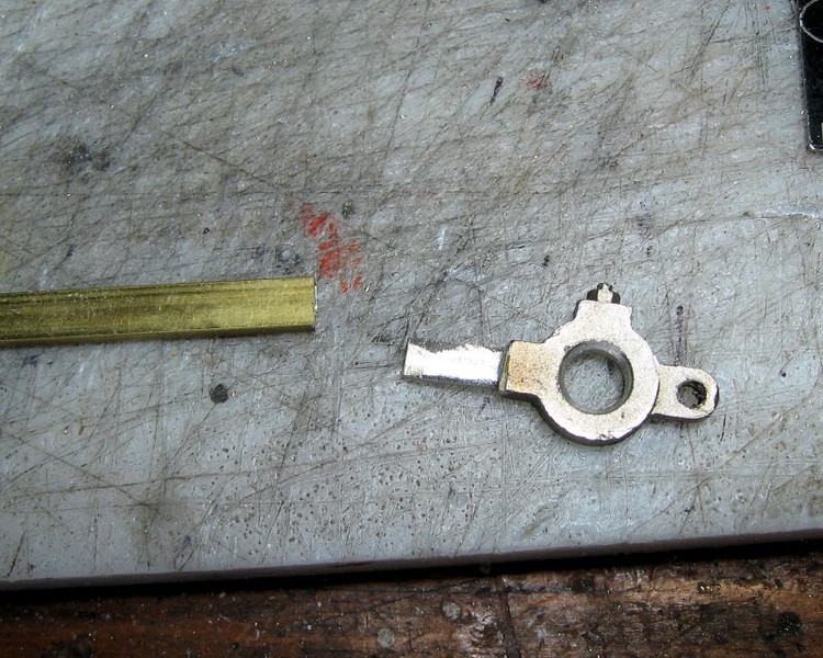
Here is what I came up with Saturday Nite…
The finished set rear side rod and front driver…
Forgot to add that I filled the tube ends with solder so it is a solid piece…
I was going to ask. You don’t want two sharp edges running on the plastic crank pin.
I think you got it nailed.