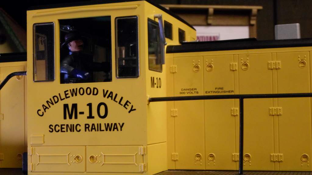
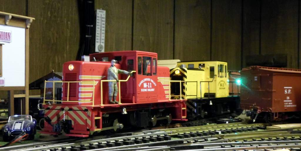
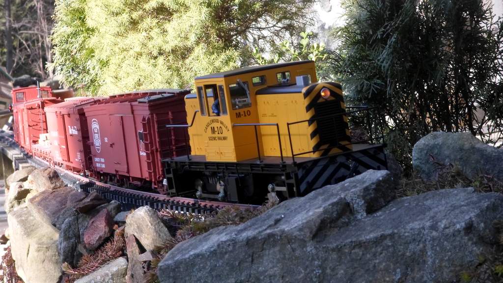
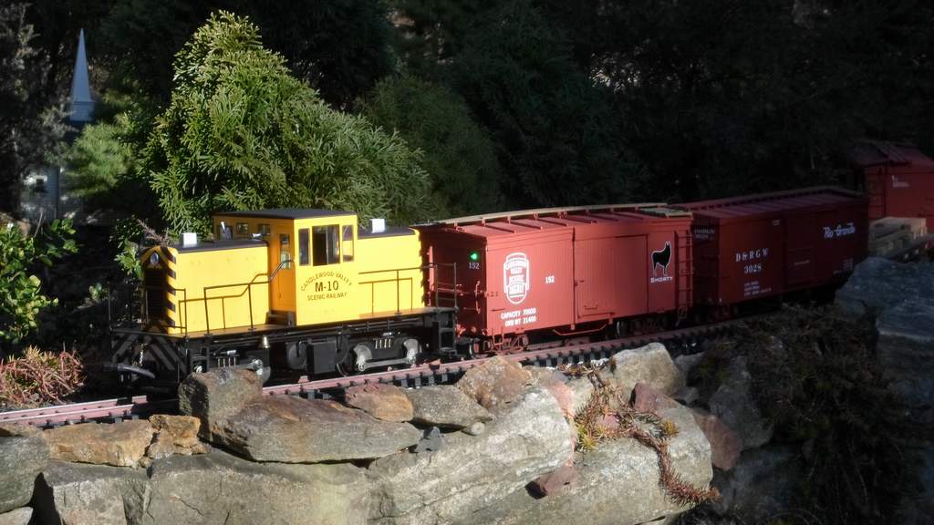
The C.V.S.Ry. has a fleet of two General Electric 45 Ton Type IV-B2 Industrial Locomotives that have seen intermittent service since their arrival on the property in 2005. Numbered and lettered for the Canldewood Valley Scenic Railway, M-10 and M-11 have both been out of service since late 2014. M-11 was relegated to the dead line due to coupler draft gear problems and has only recently returned to service as reported in this thread . M-10 was fully torn down in 2014 for electrical upgrades. Due to budget and staffing issues it has seen nothing but a fresh coat of dust until now.
The goal for M-10 was to A) Remove all original electronics and smoke. B) Re-wire the body and replace white LED headlamps with CVSRy’s standard amber LEDs C) Add a speaker in the font hood for sound that originates in a trail car and include provisions to drive the existing speaker in M-11 for MU operation. D) Update coupler draft gear to be identical to M-11 and E) Repair any cosmetic damage.
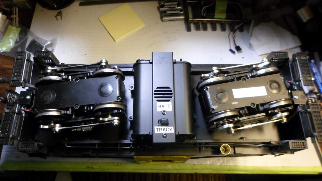
Tear-down and design of the speaker upgrade was completed long ago as well as removal of factory electronics and completion of chassis power wiring. What remained was to build the speaker enclosure, swap out the LEDs and set up body wiring plugs. Also, the original multi-unit sound plan needed re-work due to the discovery that the on-board loco speakers are 4 Ohm, not 8 Ohm.
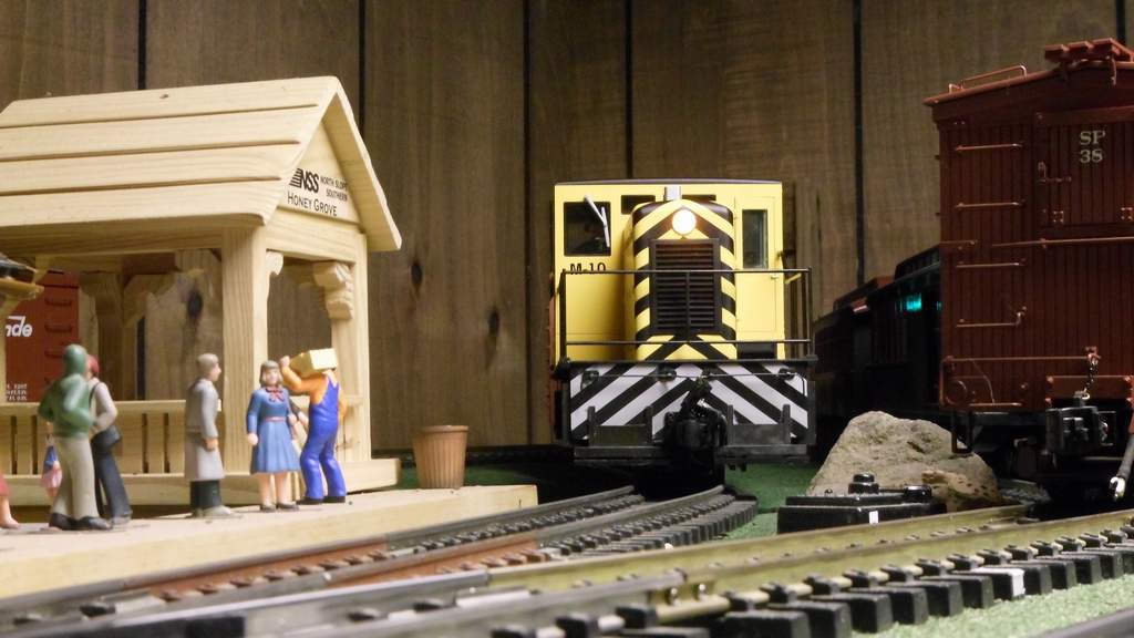
Over the last 10 days I’ve spent most every evening on this project and have finally gotten to the point of operational test today. I’m happy to report that after a brief bit of confusion over implementing the wiring plan, the operational test was successful. So without further pontifiaction, I present the latest spy photos from the CVSRy shops.
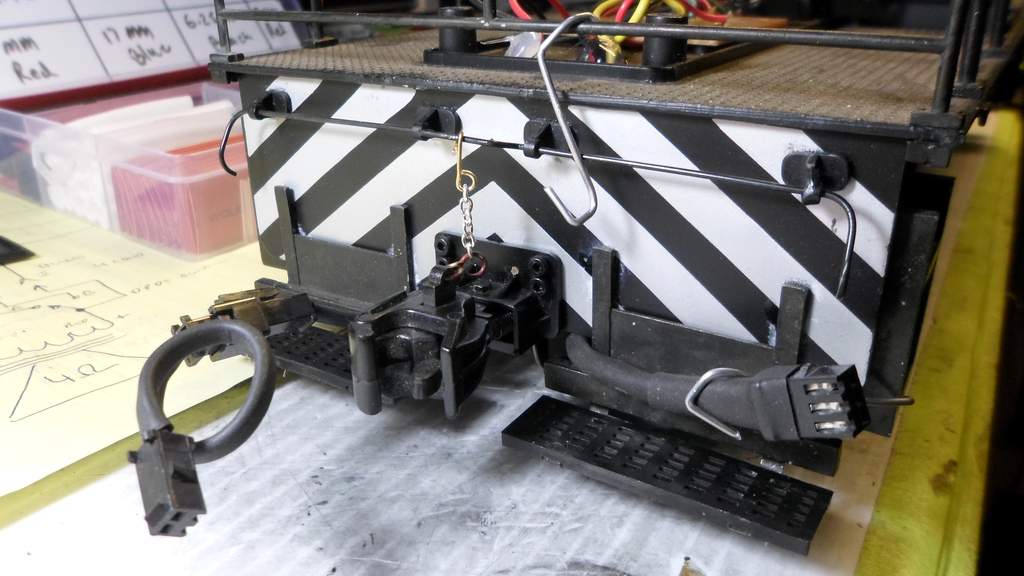
Step one was to install a new three conductor train line for the sound circuit at the front and back of M-10…
Next, Install our standard Accucraft coupler and add function to the lift bar…
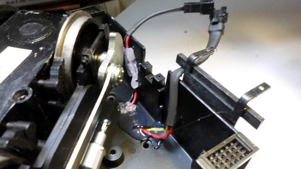
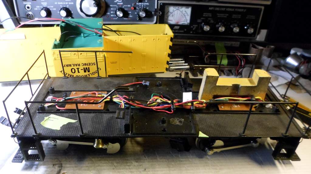
Next was remove the factory white LEDs and replace them with my standard amber LED and an in-line resistor. Hot Glue and Heat Shrink Tubing are staples in the C.V.S.Ry. Electrical Shop…
Then wire everything together with a plug for the chassis attachment. Note that the rear LED (at left) is reverse polarity to the front one for directional lighting…
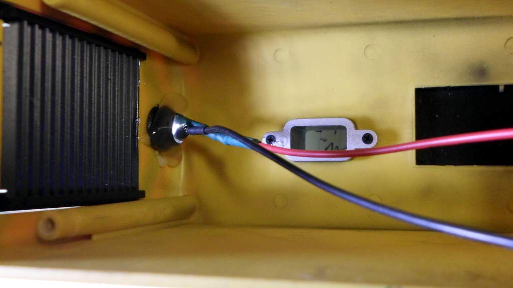
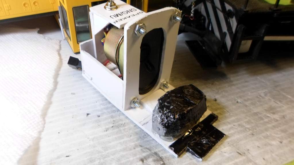
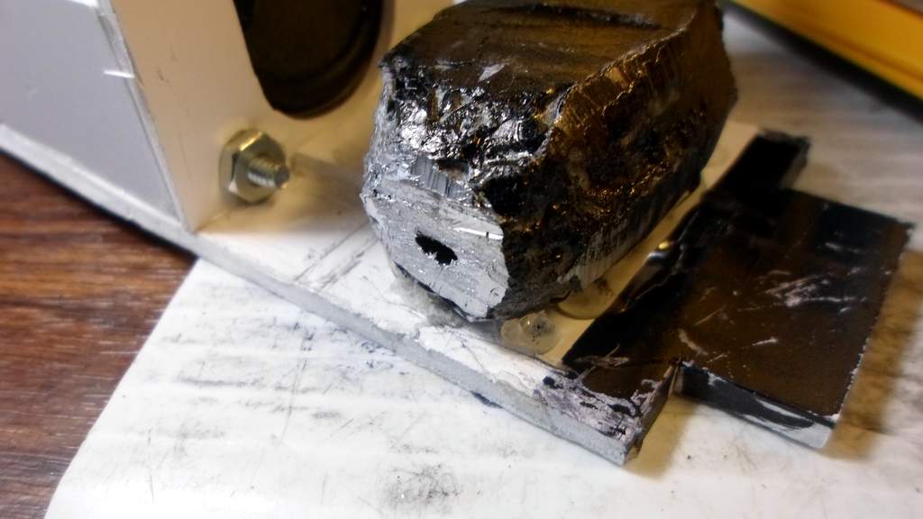
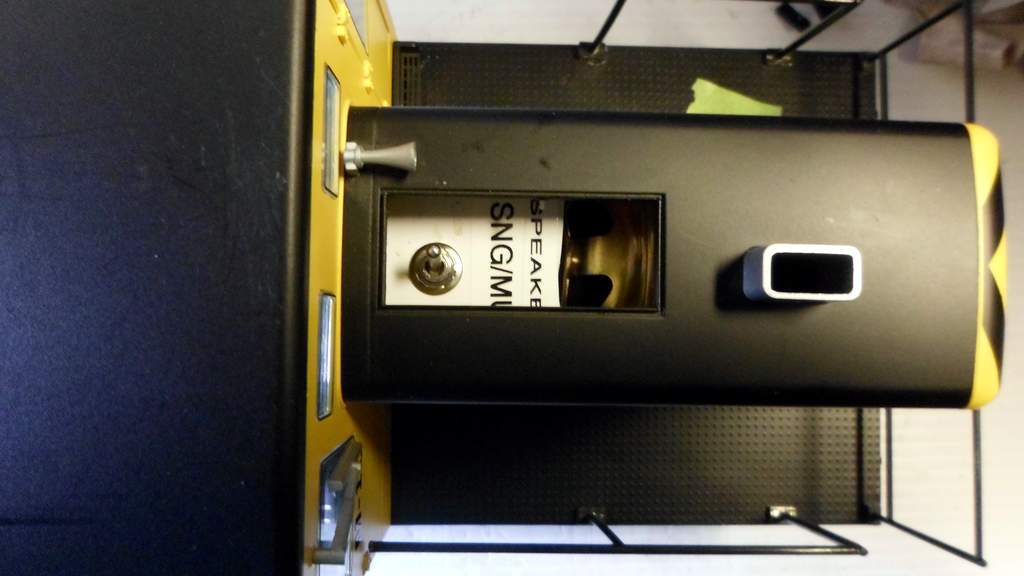
Next I built a speaker mount based on the design I came up with for M-11 a few years ago. This version incorporates a DPDT switch to change from parallel to series wiring of the locomotive speakers depending on if one or two locomotives are connected to the trail car’s sound board…
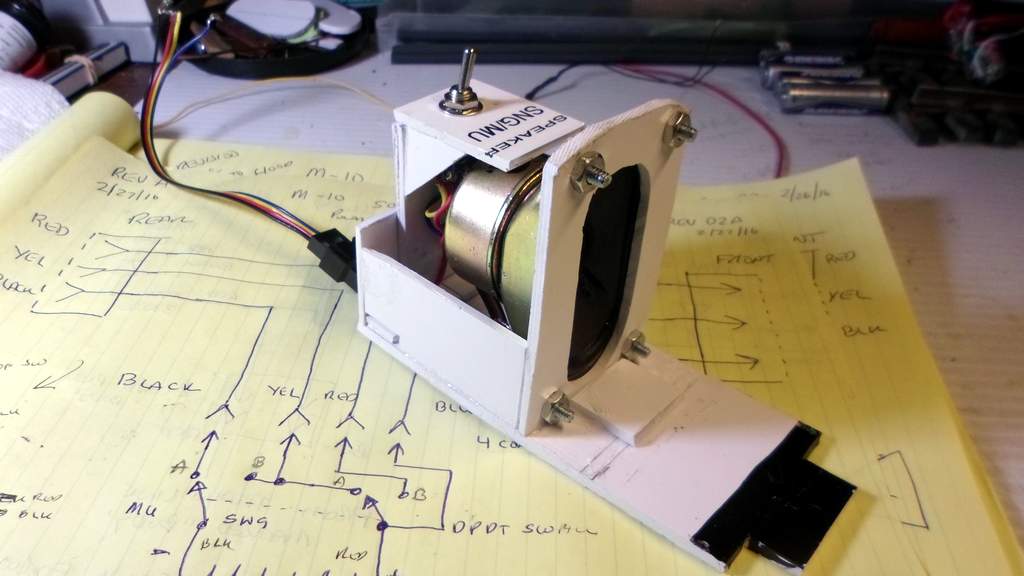
The switch is accessible via the removable cover in the front hood. The 4 conductor cable with plugs is a computer fan extension cable from Startech via Amazon. Next the train line for sound was wired up with the 4 conductor plug per the intricate wiring plan…
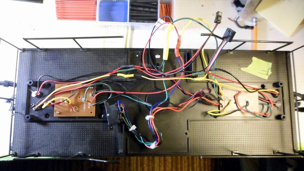
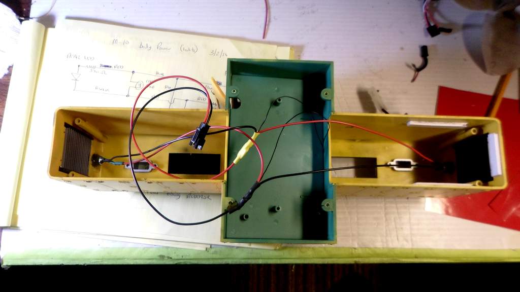
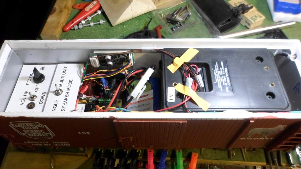
Before operational tests could be conducted, “Shorty” my Battery/Sound trail car (I call it an HEP car) needed to be modified with the addition of the MU switch and changes to how the sound train line connector was wired up internally…
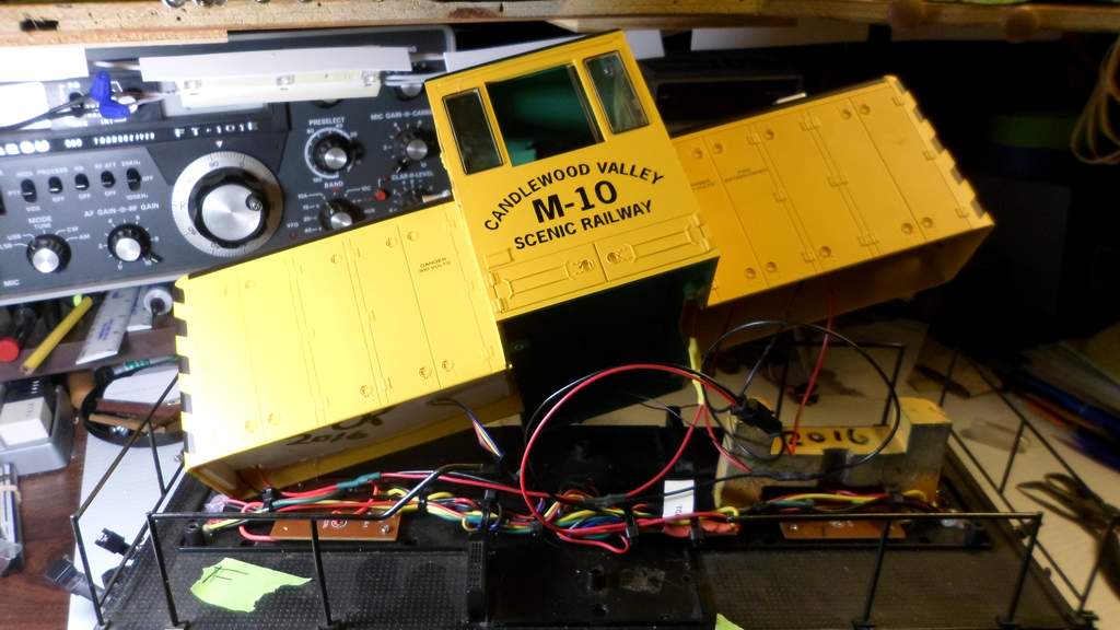
With this complete I was able to run operational tests around the indoor layout without the M-10 body to confirm my wiring plan actually functioned…
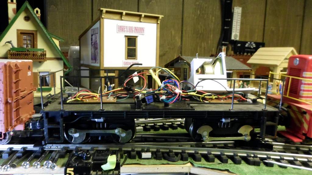
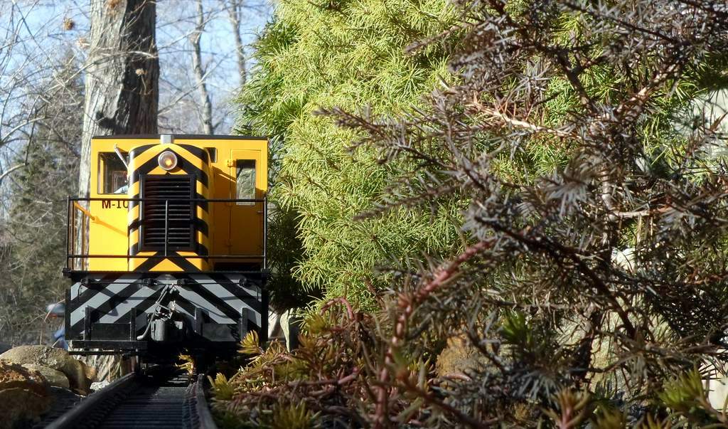
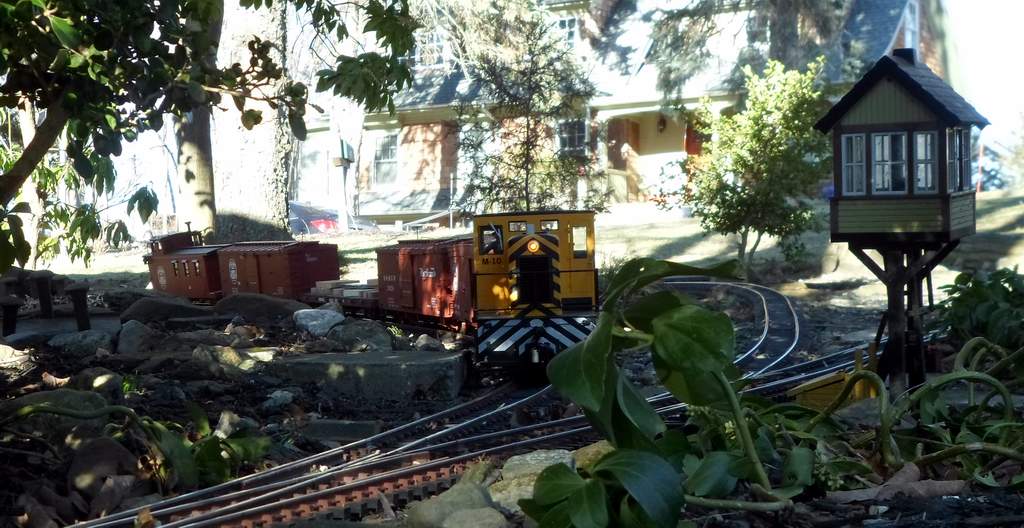
The tests passed in all supported modes so tomorrow the shop crew will be tasked with placing the body and road testing.
