Good Evening Gentlemen. I have gotten this from a non active forum http://yourmodelrailway.net/view_topic.php?id=2843&forum_id=74 this seemed pretty simple however it doesnt work correctly i have tried three times. I choose this module because my electronic skills, well put it this way, i am needing special ed for that, can some help me?
This is really going to take hands on debugging.
When you trip the reeds, and leave the magnet there, do the leds light?
Greg
Greg, Red light stays on all the time, and yes when you power up transformer, trip the first reed switch it goes out and then next light comes on which is yellow, doesn’t do. you think Green signal hit the reed switch, Red, second reed switch change to yellow, and so on. What is odd. if you look at the pin set up, what is there to hold the light lit ?
anyone else have any ideas, it looked really simple, when saw the crossing of the pins from one relay to the next believing that it made it work as a latching relay, keeping that color led lit until it trips the second reed switch chaning the signal. 3 color aspect. green signal, then should drop to red, then to yellow back to green, eventhough it has 4 aspect double yellow approach. looked like the sequence was off and the leds did not stay lit. i tested the diodes and they were correct and tetsted each relay they all worked find inckuding the reed switches, and the resisters are correct. i even changed to regular 12 volt color lights to besure it wasnt the leds.
thank you bill
There are other choices for yellow signals. Being able to stop with in the visible trackage and able to stop at next signal, both allow ‘slow proceed’, depending on whose road.

Happy Rails
John
This looks like the same circuit that I came up with many years ago and posted on LSOL/MyLargeScale. I guess someone saw it and decided to build it, or GMTA! I wonder if I still have my pics. (http://largescalecentral.com/externals/tinymce/plugins/emoticons/img/smiley-wink.gif)
Edit:
Guess not. Must be on the old system.
Hello Jim
Just worked a 12 so i got home late -
Looked at the schematic vs pics of wiring
they don’t match up -not sure yet which one works
as Greg said this would be more easily resolved in person but lacking that option
i think that i will have to build the thing to troubleshoot because the relay latching
circuits are difficult to follow in sequence.
In the mean time power up and try tripping the green reed switch then see if the sequence works
the green seems to initiate the sequence. see if the lights stay on.
Bill
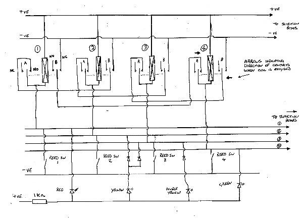
placement of reed triggers for double yellow system IT SHOULD WORK AS DRAWN

Bill I will give a try, I would like eliment double yellow altogether. Shouldn’t the first signal be green ?
Hello Jim
The signal will be green until the train gets close enough to the signal to trip the yellow approach trigger.
as it passes the signal the aspect turns red
when it goes into the second block, it trips the yellow and the aspect goes from red to yellow
when it reaches the third block it trips the green trigger and the aspect turns green awaiting the next train.
a “block” is typically at least one train length.
Bill
gentlemen i got it to work thank you. but can someone tell me what the diodes aredoing. because i am not using them
The diodes protect the LEDs. LEDs, while operating as a diode, do NOT have a high reverse voltage, so when the opposite polarity is applied, they can short.
Greg
okay. all. this module works on the bench but when you start to put it together with the reeds. i am totally confused. hows the bus sire the reed switch determine with signal gets which color. as. i keep reading on and re-read it i het more confused this guy wasnt clear at alk this is a simple understanding module. more help please.
gentlemen I believe I have figured it out. the beginning of the automatic signing block, the author kind twisted and turned the project around. can a few of the good electronic modelers read that article i swear it took two months to figure this out
I looked at the schematic, and it seemed it worked in one direction only, does it work in both directions?
Greg
Hi all
To make the signal bi-directional would require an additional set of triggers (reed switches)
The signal aspect depends on which trigger is activated.
Bill
bill and greg i need some. help i have been working on this to the point that i am tired of burning my fingers from solding so much. i even took a. 1 by 2 furing piece of wood nail 6 wires. as the. core cable and then confuss what goes wher. when re-reading all of the directions and looking at the diagram they dont correspond. so the cable has 6 wires. black is neg- and is connect to the reed switches. the other of the reed switch is then connect to what ? the black neg from the sign or to the r y b g cable . when i do the is always a wire left out where does that go. the author writes, " the reef switch for each signal is wired in common with the red aspect. orginally the authur says. you only need 3 diodes for the. yellow and. double yellow (which i’d like. to eliminate with only red yellow and green signals). but writes later on on the diagram he has diodes for each signal post. i can wire the bench model no problem but when i start to wire on a test track with all 4. blocks i am confused with where is the hot postive wire going to ? i also notice when test with a wire on the bench model, you can cross polarity with the relays and get a different combination of signals. if you construct this module. you maybe come uo with an extra wire. please help i am ready to throw everything against a block wall, which is sonething. i havent done in over 35 years. .
bill and greg i need some. help i have been working on this to the point that i am tired of burning my fingers from solding so much. i even took a. 1 by 2 furing piece of wood nail 6 wires. as the. core cable and then confused what goes where. when re-reading all of the directions and looking at the diagram they dont correspond. so the cable has 6 wires. black is neg- and is connect to the reed switches. the other end of the reed switch is then connect to what ? the black neg from the diagram or to the r y b g cable . when i do the i always a wire left out, where does that go. the author writes, " the reed switch for each signal is wired in common with the red aspect. If the signal links are postive white wire where is it going and isn’t cross circuit pos to neg. orginally the authur says. you only need 3 diodes for the. yellow and. double yellow (which i’d like. to eliminate with only red yellow and green signals). but writes later on on the diagram he has diodes for each signal post. i can wire the bench model no problem but when i start to wire on a test track with all 4. blocks i am confused with where is the hot postive wire going to ? i also notice when test with a wire on the bench model, you can cross polarity with the relays and get a different combination of signals. if you construct this module. you maybe come uo with an extra wire. please help i am ready to throw everything against a block wall, which is something. i havent done in over 35 years. i even brought 6 wire termal strips for each signal tower. or post. wire up. red yellow blue green. white and black. but if if the reed switch is wire up to the red aspect in common the white wire on the termal strip is never used . or I’m just so confused at this point i should just put it away.
I knew that I had addressed this before. Turns out it was in 2010 and the system I designed didn’t even need reed switches.
It works on the “Tortoise Bump” track gap system. The Red/Black “squares” represent the railroad track and yes, the relay voltage is applied directly to the rails as shown and won’t interfere with anything, assuming it has its own power supply. As a train passes it sets off the sequential relay while turning off the prior relay. It’s been years since I’ve looked at this, but it may work in both directions.
As I recall, the only caveat was that a train approaching from behind would interfere with the other train’s signal, but I would have to look at it again and give it some thought.
Relays can be any voltage and their power supply is matched accordingly. I would do this using 6 volt relays and a 6 volt wall wart, and it could also power the signal bulbs.
The “free armature” on the relay is what you use to activate your signal…, or whatever. Or, for that matter, it could also be used to break the connection to keep a train from running into the prior block, and the LED/bulb for the signals simply tied into the relay’s current.
With some thought, there are lots of options.
