Large Scale Central

Some More Electrical 101

First thanks to all for your help and I hope I am not wearing anyone thin. I am learning a ton about electronics and electricity which I know next to nothing about. So here are some other questions.

Thanks to what I have already learned from you guys and online I understand the difference (at least vaguely) between voltage, amperage or current, watts, and resistance; and how they play together with Ohm’s Law. So to ask the question I will first illustrate what I am working with and what I would like to do if possible. I have acquired a power unit out of an old computer; 115v in and is rated to produce 12v@8 amps and 5v@20 amps. Measured I get 11.5v and 5.1v so basically its doing what it says it will do; I haven’t measured the amps, not sure how. The main purpose of this project is to learn and play with something unfamiliar(and try not to kill myself). Beyond that I want to see if I can build a resistance soldering unit and have it double as a DC power station for testing or otherwise playing with stuff. Now for the resistance soldering unit I know that Watts is what I am after on the Ohm’s law equation, that’s the heat I am going to need. 12V at 8A produces 96W and 5V at 20A produces 100W.

First question: Am I right in thinking that using the higher voltage and lower amperage to produce basically the same wattage would be preferable because it would put less strain on the circuit and not require as heavy duty components? Given the choice of the two sources wouldn’t the 12v 8A be the better choice for the soldering unit?

Second question: Does amperage, or current, increase as resistance is added? Does voltage drop as resistance is added? I would think the answer to both questions is yes, but I really don’t know, why I think that. When I go to apply the current to the work I am soldering there will be an added resistance (that’s what we want so it will heat up right?) and I am making an assumption that this will increase the “load” and require more current (amps) to push the electrons through? Or am I totally off base? Basically where I am going with this is will I need to protect the circuit so that when the load is applied I won’t get a spike in amperage and burn the system out. I am using all 15A rated stuff based on the 8A rating and am thinking a fuse or circuit breaker on the soldering leads is in order to protect say for a 10 amp load. But in that make it a slow blow protection so that it will take the momentary charge for soldering but cut out if things go horribly wrong. To take it a step further could, or should, a person put in a slow blow 10amp circuit protector to allow the soldering but then in series put in a 15A fast blow for an instant protection in case of a large surge? After all soldering is creating a short on purpose so we have to allow some of it but we don’t want it to go beyond the capability of the system right?

Third question: Both for soldering and for a generic DC power supply having the ability to vary the voltage would be nice, albeit for different reasons . I do know that lowering incoming voltage to a transformer also lowers its output. In all of the things I have read about building these things there is mixed opinion on how to do this. As I am trying to use inexpensive on hand or off the shelf at Home Depot items, the idea of using a dimmer on the AC side to lower AC input voltage seems like the ticket but has had its detractors. Since I am going to protect the circuit for 15 amps max can I use a 15 amp dimmer on the AC side to control DC output voltage reliably?

Fourth question: This is the one I am most concerned with. Up to this point everything has revolved around the 12v side of the equation. I have and would like to use the 5v side of things as well. But at 20 amps it is way more current than I would ever use for low voltage applications and do not like the idea of such a high load on the system and it components when it is unnecessary. So can I, and what would be the best way, to maintain voltage but reduce the amperage down to say only 3 or 4 amps? Is it as simple as just adding a resistor? and if I do add a large enough resistor to knock down the current how much, if any, of a voltage drop would I see across said resistor? Is there another relatively simple way? The other idea is to just not use it at all and only use the 12v side and drop it down like mentioned before. It is there just seems like I should use it for something. Is there a variable resistor so one could control amps on demand?

Last question: measuring amperage. Does the power source need to have a load applied in order to measure it? Or is simply connecting the leads to each of the wires going to give me the amperage. Also this goes to the idea of adding resistance and changing the amperage. With no load on the system will I be getting an accurate reading? Or would I need to drop a resistor of some sort (piece of brass) to create the load in order to measure it?

I think that’s all I have for now. Thanks ahead of time. I hope people view this as a chance to give an education and not treat this as annoying.
I am a mechanical type but in response to the second question, the current actually goes down as resistance is added…

Consider a bar of copper… Essentially zero resistance, all the possible current would flow… And the voltage drop from one side of the bar to the other would be very small.

Now consider a string of Christmas tree lights. Each bulb connected to its neighbor in series… Lots of resistance, little current flow, large voltage drop.

As to soldering, the wattage of the soldering iron is the voltage times the amperage. Note that a 35 watt iron made for 110volt house voltage is made differently then one made for 12volt power. What is different? the resistance heating wires will be smaller and longer in side the 110v iron (more resistance) it will only need about 1/3 of an amp of current (35/110) the 12volt 35watt iron will draw about 3amps.

Finally, I guess your power supply has quite a bit of power. That means the wires inside are big enough to carry the necessary current without producing so much heat that it doesn’t melt stuff. Power supplies use transformers which consist of two coils of wire intertwined around a magnetic core. One wire for the input power (from the wall) the other for the output. The relative number of loops in each coil control the relative voltage. The thicker the wires the more current that can safely pass.

Devon, Eric is right, the more resistance, the less current, for the same input voltage. So your 5 volt tap can output 20 amps, but it doesn’t have to. If you have one 5 volt bulb on it, then it will only output what that bulb allows to pass through it, probably like 200 miliampres. So the question about the 5 volt part of the supply is really not a valid question.

For resistance soldering, the work would have nearly 0 ohms. I would think a good, wire wound resistor in one of the leads would be what you would need to keep the current where you want it. A breaker would just trip.

On a regulated power supply, like what you have, you cannot vary the input to vary the output. You would need to adjust the output. You could use a regulator and a pot, or a power transistor and a pot, to vary the output. If you try using a dimmer to reduce the input you will either not succeed, or you will blow the dimmer, or power supply, or both.

Back to basics. Current (I) equals voltage (E) divided by resistance ®. I=E/R Given that the voltage from your power supply is constant, the amount of current drawn is inversely proportional to the amount of resistance placed across the terminals of the power supply.

OK so in a layman’s first grade understanding of what was just said is that the 20A is the systems potential to produce that current but in reality it will only produce what the object being powered will allow or ask for if you will . So as long as everything operating on the 5v side of things is not drawing more than 15 amps I should have to worry about it burning stuff up. That seems straight forward on the 5 volt idea

Now for soldering with the 12v side. Now are you saying I will need to put some sort of resistance on the lead to get it to work? or are you thinking for circuit protection? How is resistance soldering working if the piece itself is not providing the resistance? What causes the piece to get hot if the current flows through it with ease? I guess I was making the wrong assumption that the material to be soldered was creating resistance and therefore heating up. If that is not the case then am I going to be adding a wire wound resistor to one of the leads that will generate the necessary resistance to give me the current I need to develop the wattage? So using Ohms law if I have 12v and want 80W that means I need 1.8 Ohms of resistance which will produce 6.6+ amps. So would I wire a 1.8 Ohm resistor in place and that will give me the 80W( i am making up a number here for educational purposes)I need for soldering?

And if that is the case then instead of variable voltage, where I was headed before, is there a variable resistor that I could dial up or down to create more or less wattage for soldering different materials. I would have to rethink its use as a variable DC supply but at this point that is secondary. I want the control, at the end of the day, over wattage. I was only hoping to kill two birds with one stone by making voltage the limiting factor but if I understand this know it seems I would be far better off adjusting resistance than voltage.

Am I on better track know. We can come back to variable voltage later if need be. One concept at a time.

Devon Sinsley said:

layman’s

For variable resistance I would need a Rheostat right?

I am not exactly sure what is inside the resistance soldering set… It may not be so simple. Certainly if you put two wires on a metal object you will get a short circuit. Low resistance=high current=smoke and fire.

I would purchase a soldering rig and use it as designed. Perhaps you can buy a 12volt set and perhaps your power supply has enough juice, but don’t count on just touching the wires from the power supply to you project and expect success unless sparks are what you are after. (http://www.largescalecentral.com/externals/tinymce/plugins/emoticons/img/smiley-surprised.gif)

Yes, a rheostat would be needed at those current draws. Since the work pieces aren’t just one piece of metal, there would be some resistance there, not much, and that would create heat. But I am not sure exactly how a resistance soldering set works neither. I would google it and see what comes up. I know I have heard of folks making their own resistance soldering rigs, but I would not want to tell you to make it a certain way and be wrong, since I really don’t know the ins and outs of such a system.

I do know, that simple circuit breaker will do its job, and break the circuit, so that won’t work. And I know I once welded jumper cable clips together by accidentally having them clipped to each other when I connected the other ends to a car battery. I was maybe 10 at the time. So I know that that resistance soldering shouldn’t be too much more complicated then that, but I don’t know the specifics.

Eric Schade said:

I am not exactly sure what is inside the resistance soldering set… It may not be so simple. Certainly if you put two wires on a metal object you will get a short circuit. Low resistance=high current=smoke and fire.

I would purchase a soldering rig and use it as designed. Perhaps you can buy a 12volt set and perhaps your power supply has enough juice, but don’t count on just touching the wires from the power supply to you project and expect success unless sparks are what you are after. (http://www.largescalecentral.com/externals/tinymce/plugins/emoticons/img/smiley-surprised.gif)

Eric,

While I understand your concern there is actually quite a bit that has been written about building resistance soldering units and really they are pretty simple in design. It is a controlled use of resistance to the flow of electricity to create heat that does the work. It indeed intentionally short circuits the system and absolutely is meant to generate heat in doing so. That’s what melts the solder. All soldering is resistance soldering in a way. An iron creates resistance and the tip heats up and you transfer that heat to the object your working with. Resistance soldering just makes the piece your working with the part that heats up. This happens quickly and efficiently.

The issue is have control over that short circuit. That’s why we are not arcing 240v and 100 amps across the piece for ten minutes. That’s where the resistance solderer comes into play and why all my questions. How does one control this and it really isn’t that hard in theory, the theory I am getting a handle on. From my understanding, and I am still learning so don’t take this as gospel, is that Watts is the “energy” (not sure that would be the correct term) that is produced in a circuit, it is the heat that the system is going to produce. We want to produce that heat in a large enough quantity to melt solder. So by controlling the voltage amperage and resistance in a system we can control the wattage produced. Mind you the big part of this equation that has not been talked about yet is all of this is over time. The concept of resistance soldering is to create just enough of a situation to generate only the amount of heat necessary to melt solder and for only the amount of time that it takes to do it. So a 12v source pulling 6 1/2 amps with generate 80 watts which is more than enough to heat up small to medium pieces in a quick hurry, couple of seconds at most. You use a momentary switch like a foot pedal to apply the current then as soon as the solder melts you kill it. If the system is sized adequately to handle the heat produce on the system for this short period of time then boom you have a resistance solderer.

That’s the theory anyway. I am actually quite respectful of electricity and honestly this one seems very doable and even more so now that i am getting a grip on electrical theory. When you think about it short circuits and resistance is all around us. It is a matter of controlling it. We have light bulbs, ovens, heaters, soldering irons, smoke generators, any heating element is some sort of controlled short circuit.

There are articles on building a resistance soldering unit. Google them and save yourself time.

Normally computer power supplies are not a good choice for this, for many reasons which I won’t go into.

Remember V=IR when you ask questions about increasing one and if the other increases…

P=I**2 R or P = VI …

If you look at the equation, you can see what happens … with V = IR if I stays the same and you increase R, then the other side must increase also to stay equal…in fact doubling the resistance must double the voltage

V = IR is the same as 2V = I times 2R… since dividing both sides by 2 gives you V = IR again.

Greg

David Maynard said:

Yes, a rheostat would be needed at those current draws. Since the work pieces aren’t just one piece of metal, there would be some resistance there, not much, and that would create heat. But I am not sure exactly how a resistance soldering set works neither. I would google it and see what comes up. I know I have heard of folks making their own resistance soldering rigs, but I would not want to tell you to make it a certain way and be wrong, since I really don’t know the ins and outs of such a system.

I do know, that simple circuit breaker will do its job, and break the circuit, so that won’t work. And I know I once welded jumper cable clips together by accidentally having them clipped to each other when I connected the other ends to a car battery. I was maybe 10 at the time. So I know that that resistance soldering shouldn’t be too much more complicated then that, but I don’t know the specifics.

David,

Your helping with the part I need the most help on and that is the electrical theory. I have read quit a bit on how and why resistance soldering works. I mean a guy built a great working unit out of a battery charger. There are more sophisticated designs out there. I understand the concept I think quite well. Very simply resistance to flow creates heat, heat melts solder. All soldering and welding are resistance based. You create resistance to create heat which melts metal. In a soldering iron you create heat and then transfer that heat by conduction to the piece your working on and it melts the solder. With resistance soldering you pass current through the piece itself to heat it up bypassing the inefficient conduction aspect. The piece becomes the soldering tip. I get the idea; where I am working from is how to control the system so that the heat production is controllable and usable instead of wild and crazy.

Your help in explaining how to control the situation is most helpful. I have the utmost confidence that I will be able to do it. I might have a few sparks and smoke and maybe a fire or two until I figure it out but I will figure it out. I am not charting new territory I am just being cautious in my application so that I can minimize damage and most importantly not light myself up like Chernobyl.

Greg Elmassian said:

There are articles on building a resistance soldering unit. Google them and save yourself time.

Normally computer power supplies are not a good choice for this, for many reasons which I won’t go into.

Remember V=IR when you ask questions about increasing one and if the other increases…

P=I**2 R or P = VI …

If you look at the equation, you can see what happens … with V = IR if I stays the same and you increase R, then the other side must increase also to stay equal…in fact doubling the resistance must double the voltage

V = IR is the same as 2V = I times 2R… since dividing both sides by 2 gives you V = IR again.

Greg

Oh trust me I have been googling. And I have seen where they have been made with battery chargers, basic transformers and even computer power supplies. And while there are articles on them, one really good one using a battery charger, like said in the beginning this is as much about learning than it is producing a solderer. Honestly I good old fashion soldering iron or torch will more than meet my needs. So why build one . . . because it is out there to be done and it is fascinating learning the theory behind it and putting it to practical application. I mean do you just like to tinker and learn? Don’t you just like the satisfaction of knowing you built something that actually works? Don’t you like trying something that is on the fringe? Some people don’t but I think I know you know what I am talking about. This needs to be done just to see if I can do it. As long as I can approach it with a reasonable amount of safety then why not?

I am genuinely curious as to why you don’t think the computer PSU is a good choice? What about it gives you reservation? I mean when I initially started researching this I thought why not and others had done it. I mean it is a clean source of 12vDC But then one aspect of it that David mentioned is the regulated power source and not being able to control the output by controlling the input. And the ones built from them were admittedly not controllable. So is the reasoning that the transformer output can not be reasonably controlled?

As for understanding the relationship between I V an R I am coming along and admit that after asking that question I realize the error in my thinking. i was hung up on the idea that the system was going to produce a steady and constant current output. I thought the systems was going to put out 8 amps at 12 volts. The David set me straight and I realized that it wasn’t that it was going to but could if need be. Once I got that part then relationship between the three made more sense.

I am still a little fuzzy on how the system works and how it produces heat at the work piece if the work piece is producing little to no resistance. At a constant (or at least nearly constant) voltage the only thing we can control is the resistance in order to generate the current required to develop the heat. Originally I as under the understanding that it was the work piece itself that was creating the resistance to generate the heat. I was thinking about a heating element and that is why they heat up isn’t it, because they are the resistor in the circuit? But what David has me thinking about is if we create resistance at any point in the circuit then is the heat generated at the weakest link in the system which is where the short circuit is occurring and that is why the work piece heats up and not the source of resistance? If so then that makes sense because the two pieces being soldered would be where the short is occurring and once that short circuit is fuse together with solder then the whole thing will heat up until it finds the next weakest link in the chain.

Ah Ha the missing piece of the puzzle and the piece de resistance is the carbon rod. The tip of the soldering iron is a carbon rod. The work piece is low resistance and the carbon rod is high resistance and there is where the heat is created. When the carbon rod comes in contact with the work piece and completes the circuit it is the resistance of the carbon rod that is creating the heat. It is the resistor. So we don’t need current limitation because that is built in at the tip of the iron. So I am back to controlling the Wattage with voltage regulation as opposed to current regulation since current limitation will be with a fix resistor the carbon rod. And using the regulated power supply could be an issue unless I choose to very the output instead of the input.

You can get a “carbon rod” inside a carbon/zinc battery. When I was a kid, my cousin used to make arc lamps using clay flower pots this way.

Devon,

You do cover a lot of ground with these questions, and we’re only poor train guys after all. . . I did spot a couple of issues/misunderstandings for your consideration.

"controlling the voltage amperage and resistance " - one doesn’t control the amps except by controlling the volts and ohms. Ampere’s are a measure of the current (electrons) flowing because of the voltage and the resistance of the circuit. You can’t measure the amps from your power supply without a resistance applied - and then the resistance defines what the amps will be, so you know beforehand what you can expect. Ohms Law again. If you don’t know the specific resistance, then an ammeter in the circuit will tell you what is going on. [An ammeter is a very low resistance meter in series - you don’t want the meter to affect the current reading. Conversely, a voltmeter is a high resistance device in parallel. ]

"I guess I was making the wrong assumption that the material to be soldered was creating resistance and therefore heating up" I hope you now realize that this is the correct assumption - though in fact it is the resistance of the joint that is making it heat up. The joint has a low resistance (usually) and therefore a high current flows through a small area which rapidly gets hot. [Side note: high current - lots of heat in most situations. VxI = Watts = energy = heat.]

“the piece de resistance is the carbon rod. The tip of the soldering iron is a carbon rod. The work piece is low resistance and the carbon rod is high resistance” Nope. The carbon rod is effectivly zero resistance - but it doesn’t stick to solder, hence the carbon!

What you are missing is that the resistance soldering rig is a controlled short circuit.

At the point of contact, there is a joint that is higher resistance than all the other joints in the system [which is not to say that the joints at the foot pedal and at the power supply won’t get hot as well as the contact point! It depends how good the joints are and how much resistance they have. But the other joints aren’t brass or similar solderable metals, and there is no flux or solder in the joint.]

When you hit the foot pedal, you are making a short circuit. The joint will heat up, the transformer will start to heat up, as will the rest of the resistive joints. Only the soldering point has flux and solder so it solders that point together. Hopefully, you took your foot off the pedal before the power supply overheated.

There’s nothing wrong with a short circuit - it’s not pre-ordained to produce sparks or melt the wires. As long as the 12VDC circuit is only shorted for a second or two there won’t be a problem.

"I am genuinely curious as to why you don’t think the computer PSU is a good choice? What about it gives you reservation? " They are not easy to control. You need to be able to limit the output current. A transformer is made with copper wire (resistance) that will heat up as you apply the short circuit at the resistance soldering site - but it won’t explode unless you keep your foot on the switch for too long.
My understanding is that a computer PSU is a switching power supply, using electronics not a transformer. If you short it some of the electronics will melt or its internal fuse will blow.

It helps to understand that everything in a circuit has resistance to the flow of electrons (current.) The power supply, (battery, transformer, PSU) and even the joints between the wires - solder has a different resistance from copper. A circuit is usually drawn as a closed system and from that you may be able to calculate the current flow through the various resistances. One of the resistances just happens to produce a voltage as if by magic, and that gets the current flowing.

Todd Brody said:

You can get a “carbon rod” inside a carbon/zinc battery. When I was a kid, my cousin used to make arc lamps using clay flower pots this way.

I have a couple carbon rods coming by mail thanks to to Craig.

Pete thanks a bunch. . .poor train guy huh? you have been a huge help in the electronics department.

A few points you brought up. I did know that you could not “control” amps but rather control either voltage or resistance and there by effect amps. I just didn’t word t it right. But what I was not picking up until David and you brought it up is that the amp rating of a device is what it can produce not what it “will” produce. That changes things a lot at least from my understanding it better.

As to my wrong assumption about the resistance at the point of soldering yeah I back to my original understanding kinda, that it is the actually the joint that is providing resistance not the materiel itself but the joint itself. Thanks for setting me straight on the carbon rod being low resistance. This confirms for me that I am understanding this better.

This is an old power supply like early to mid 90’s style. I am pretty dang sure it has a transformer in it (looks like every other transformer coil of wire do hicky) and It is not a switching PS at least as how i understand what that means. My understanding of switching PSU is that they require a load to turn on. This is not the case with this one; you flip the switch you have power. 12v and 5v with no load, unless the fan is enough load to turn it on.

Now I do get the idea thanks to David about the regulated power supply and not being able to control the input voltage. So if I use this as a variable power source I see why I have to control the output voltage and why it is so much more difficult to do. But being stubborn I know it can be done, I am not charting new territory, so I want to at least burn the thing up trying. It was free, anything else will cost me money and this is one big learning experiment anyway. Now those who have come before me have been vague as to how they are controlling out put and from what I can gather they aren’t; their machines are one output and they are quick on the switch. Now with that said the highest this can put out will be 96W so that is not a very powerful resistance solderer at all in fact it would be on the low end of a hobby model. So in reality I may not have to regulate the output at all at least for soldering.

But still being stubborn and with another clue from David about using a pot (I actually new what that was surprisingly) I did some further reading and a guy was making a variable DC power supply with a step own transformer and a bridge rectifier. I am just proud of myself beause now I also know what that is and it makes sense to me. But at any rate it includes a couple of caps and finally uses a Pot and a Filament resistor in combination to vary the DC out put from 20v to 0v his transformer produces 24v. So in my situation I think I very easily can control my already smooth DC output with the same set up. In fact I think my power supply is exactly the same set up as what he is describing minus the Pot and Resistor. I would have to look closer but I think they are using two step down transformers and a rectifier and a few caps. I believe they are in there. So if that is the case I think I am in business.

Thanks for the help. and any other advice you have along the way is appreciated. And if it works we can all sit back in amazement and if it doesn’t . . .Well everyone can get a chuckle about it and I will dig out my soldering iron.

Now I actually do totally get that we are trying to create a controlled short circuit. I have known that from square one and that is why all the questions. Its managing and controlling said short circuit for productive use that brought this up in the first place. It would have been easy if I had been able to just stick to wires into a outlet and touch them to my work piece (http://largescalecentral.com/externals/tinymce/plugins/emoticons/img/smiley-surprised.gif). So I knew from the outset that I was going to have to control the situation and the way to control it would either be resistance or voltage so that I could produce the wattage necessary to solder.

A hint: determine how many amps you need for the resistance unit to work, and then see what it costs to get a pot to handle this power.

Bottom line, a big transformer, that can take the short circuit current and abuse will work, a precision regulated power supply with overcurrent limiting and shutdown circuits is not a good choice.

There is a famous article from Vance Bass (early bay area (that’s San Francisco/San Jose area) large scale live steam guy, on how to make one.

George Schreyer has the pdf of the article on his site: www.girr.org/girr/tips/tips1/solderer.pdf

Greg

I think, I haven’t tested it, but I think, that for the initial application of voltage to the joint, the flux between the 2 pieces of metal may be the “resistance” that creates the heat. Watts equals voltage times current, and voltage equals current times resistance, so you need resistance at the joint, to have the voltage drop there and create the heat. Once the resistance at the joint drops to zero ohms, or close to it, there would be very little heat created there.

Honestly Devon, my El-Cheepo Weller 40 watt iron does most of the jobs I need to do. For bigger hobby jobs, I dig out the old Craftsman solder gun. I would like to see if you can make this experiment work. But I am also glad I am “watching” this from a safe distance. (http://largescalecentral.com/externals/tinymce/plugins/emoticons/img/smiley-wink.gif)

Greg,

thanks I can see where your coming from. If those power supplies are specifically avoiding the very situation I want to create then I can totally see where your going. I have read and saved the PDF of that article and that is where I started when I got sidetracked by having the computer PSU and not having a sacrificial battery charger. So I will go back to the Battery Charger (they are cheap) and use the Computer PSU for something else.

David,

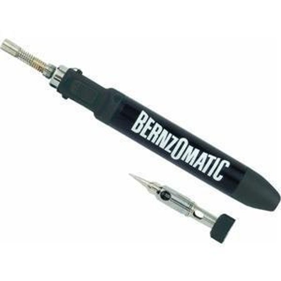
yeah my little el cheapo iron works fine also, I also just purchased a Benzomatic pencil torch

And I am practicing with it for the upcoming build. It is very cool. Acts as a torch but then you screw the tip on and it works just like an iron but heats up way faster.

So no I don’t need a resistance solderer, not sure I really even want one, but I do want to make one because I can